RetroChallenge 2022/10 - Data General Dasher 386-25K Restore

Hello all,

I’m a little late to the RetroChallenge show, but as I always say better late than never!

I’m going to attempt to restore functionality of a Data General Dasher 386-25K Model 91862 PC from the early 1990s. There’s no POST as far as I can tell but it does power on, even though there looks to have been some liquid damage after opening it. I’d be keen to play some Microsoft Solitaire if I can get this beast purring again.

Cosmetically, it looks like it’s been through a portal to hell (Doom anyone?) but I’ll be focusing on function over form. The internals look like they might have been wet at some point too. This sure will be interesting. Lots of obstacles to make it a real challenge.

To start I’m going to strip it right back, clean as much corrosion off as I can, all those little capacitors will be replaced. We’ll check inside the PSU make sure there’s nothing really bad going on in there (i.e. RIFA caps). I’ll use my knowledge of basic electronics to start and we’ll see where I end up in a couple of weeks.

I don’t have a keyboard come to think of it. That could be a problem if I manage to get it to POST…

:sweat_smile:

2 Likes

Before starting any work on the machine itself, I’ve had a look around online to try and gauge what sort of machine this actually is. From what I’ve been able to gather:

  • It’s a 386DX running at 25MHz.
  • It has space for a 387DX co-processor.
  • There’s an Intel 82385 cache memory controller.
  • It can take up to 8MB RAM onboard (1MB x 8).
  • There’s a backward ISA slot that supports an extra 8MB of RAM on a custom card.
  • Onboard VGA is present, but I also have an ISA VGA card.
  • The power connector appears to be AT-like.
  • Shipped with Connor hard drives ~40-100MB.
  • I’ll add more links here with info as I find it.
1 Like

See that weird backward ISA slot. That’s the memory expansion slot. I’d double my RAM if I had the likely proprietary card and extra RAM. These poor RAM slots are quite damaged though. I don’t know who had this machine before me but it looks like they, quite literally, jammed in some chips. You can see the hard drive connector just next to the memory expansion slot.

Not the best example of how to install RAM! You can see the hard drive LED light cable socket (black end) to the right. You can also see the power LED light cable with PC speaker (white socket) to the right.

Here’s the power connector, definitely a similar layout to AT. White and blue are the negative rails (-5V, -12V), all the reds are +5V, yellow is +12V and orange doesn’t do anything yet. Black is all ground. The only rail that seems a little off spec is the +5V rail. Getting +4.4V, which is just outside the 10% limit. Let’s keep that in mind.

The RAM slots to the left are visibly damaged. Being nothing but plastic it was inevitable that they would crumble one day. I wonder if these can be replaced? I’ll need to look into that. Currently 4MB of RAM is installed and not popping out of the broken slots. 4MB should be enough for what we’re trying to do.

Here’s the reference AT power supply pinout. It’s different but as noted above, definitely similar. If I had to guess, I would say they did this to lock people in to buying their service parts after their warranty had expired. P8.1 and P8.2 are the ones we are interested in. The two big questions are:

  • Why is this P8.2 not giving a solid +5V?
  • Is P8.1 (Orange) getting a power good (PG) signal? and
  • If P8.1 is getting a power good signal, is it getting it fast enough?

I don’t have any oscilloscope or logic analyser hardware. We’ll have to base the assessment off the physical condition of the power supply and replace any likely, and cheap, culprits.

The batteries are a pair of CR12600SE MnO2-Li type. These batteries are dated early 1990 and haven’t leaked but are well beyond their years and show only 14mAh of charge remaining. They will be disposed of safely and replaced.

@Jon has suggested replacing them with AA or AAA batteries as they are not rechargeable. Each battery is rated at 1500mAh and 3V. Going off this, AAA batteries would be the closest match at 4x 1.5V at 750mAh giving us a solid 6V at ~3000mAh that the original batteries had.

1 Like

Unlabelled, undocumented dip switches. :thinking: That’s going to be interesting. Older terminals from Data General used similar DIP switches to control the baud rate from their terminals to attached peripherals. We do have a few ports at the back. To the immediate right of the dip switch bank we can see where the battery would normally connect. Further right of this you can just see the edge of the floppy drive connector on the main board.

Now that I know more about the machine I’ve set some time aside this weekend to clean, photograph and document the internals. I can also dump at least three of the four EPROMs on the mainboard. One of the chips appears to contain more than just code, which my programmer(s) cannot handle. It is an Intel D8742 - an 8-bit CPU plus ROM, RAM I/O, timer and clock in a single package.

1 Like

Connecting batteries in series do not “add up” their capacity. Assuming you use Alkaline AAA batteries at 750mAh at 1.5V, you will end up with still 750mAh at 6V. There may be 1200mAh alkaline AAA batteries, these are probably your best bet.

1 Like

I don’t like all that cruft and corrosion resting on the main board. But what is really worrying is this:

Look at where the fan hole is for the power supply, there’s corrosion all around it. This means I am going to have to go into the power supply and have a look. I generally avoid high voltage repairs but for the sake of playing Doom, I’ll make an exception.

For now, the main board gets to have an unconventional bath. There was an ultrasonic cleaner hanging around but it has disappeared so I’ll have to use a different type of science. :test_tube:

I dumped close to 1kg of bicarbonate onto the worst looking area of the board as the box underneath wasn’t big enough to do the entire board all at once. An alternative, and possibly better way, to do this is usually to mix the bicarb with water and brush the board, cleansing with vinegar afterwards, but it’s just not as fun.

Fizz!

Fizzzzzz!

Sizzle!

It’s a white Christmas! The side angle was to try and get some fizzing in the rear ports. I always say, you’ve got to have fizzy ports - why, it’s one of my catch phrases! I probably should be looking at the power supply voltage rails but six litres of vinegar says react that bicarbonate! :smile:

Submerge! Also see the video card hiding in there too.

This is tap water, which is less desirable for rinsing as we were only able to get two litres of demineralised water for the final rinse.

Lots of splashing around in this shallow bath to try and remove any tap water residuals.

Much better, not perfect - but it doesn’t have to be.

There’s so much I/O on this board.

From above it doesn’t look too bad at all. However, on closer inspection:

There still seems to be continuity on the traces tested, but what is going on here? Might be something to watch.

@Jon And here I am pouring baking soda and vinegar all over a main board! It’s almost like I completely forgot about series and parallel! Thank you for reminding me! :sweat_smile:

Up next, we’ll move on to the power supply and give it an initial assessment.

Delving into the power supply today. I’ve not really worked on many AC power circuits in my time. This will be interesting!

And off comes the top! We’re looking at the DC-side of the power supply. The newest/least-oldest component I can find is from week 17 of 1991. The week of 22nd April 1991. That means this unit must have been sold after that time; mid-1991.

If I were a betting man, I would say those two little PCBs help generate the Power Good (PG) signal through the orange wire and I believe that the capacitors will have high ESR, meaning they are less efficient with higher ripple current - resulting in higher heat output and failure.

On the other side of the power supply we have the high voltage section, with corrosion. Great. I can probably clean up the corrosion and coat with a chemical barrier to prevent further damage.

I do not like the looks of the corrosion on the input (AC) wires (blue and brown). It should clean up alright, let’s carry on.

Back on the DC side, we can see the rails for +12V (yellow), +5V (red) and ground (black). On the far right there is the main board DC power (thicker cables), and the multi-coloured cables next to them head to the four Molex standard 0.093-inch pin and socket power connectors.

Towards the two circuit boards on the left we have two heatsinks which have transistors providing out -5V and -12V outputs. These feed on to the blue and white cable around the middle of the board in this photo - behind the orange cable. The orange cable is the power good (PG), which is documented far better for ATX than AT, but the principle is the same. There’s a good write up on Whirlpool, a part of their Boot Sequence article. Sounds familiar doesn’t it?

But with only a month to try and complete this project (who limited RetroChallenge to a month, I ask?) we’re attacking this from all angles. Back to the main board we go.

There are 29 electrolytic capacitors (circled) on this board with four tantalum capacitors (not circled).

Here are the four near the power connector in their removed state.

And here they are replaced. We went with slightly larger voltage ratings so they would be the same width. The height is increased but they seem to fit alright. Most of the electrolytic capacitors, 26, are 10uF 50V. The two near the power feed are now 100uF 25V and 10uF 100V, YXF series from Rubycon.

The remaining capacitor is now a is 47uF 50V from Rubycon’s ZLH series. I’ll definitely be replacing the capacitors in the power supply as there is a high chance they are the cause of the fault we are seeing. For the main board though, we have a multi-layer PCB that has a ground plane the size of Texas. Replacing just those five took a long while. Will it fix our fault by replacing them now? Probably not.

Flash back! I didn’t like the looks of this one. It looks like the PVC surround is being squeezed. I should replace it. I probably will replace it.

Intel D8742 Datasheet (Page 1)

First, I will get these erasable programmable read-only memory (EPROM) chips dumped from the main board to ROMs so they can be replaced if need be (unlikely). If anyone knows of how to dump the D8742, your advice is welcomed. I’ll also investigate the power supply some more in the coming days and get some replacement capacitors (low-ESR) on order. We’re cutting it close for delivery times though. Let’s keep it going! :100:

Success! I’ve uploaded the ROMs to the file server and archived them with Wayback Machine. I still haven’t been able to work out which adapter or how I’d be able to read back the code from the Intel D8742. I’ll keep working on it.

We’re assuming the floppy drive will be dead and are still trying to source one, and some disks, for DOS and/or Windows 3.x. We have come across this little drive. A Connor Peripherals 3114 (CP-3114). Does it work though?

Yes… it does! Amazing, I’ve never seen badblocks run so quickly. This hard drive is not only era appropriate but a good candidate to match the drives that would have shipped with this machine. I’m just glad it seems to be working. Cylinder-Head-Sector (CHS) is marked as:

C 990
H 13
S 17

That’s around 107MB of storage. Some more information on this drive can be found here. We’re looking pretty good so far. Still need to work out the whole no POST thing but I believe that we’ll achieve something by the end of this project.

Next we revisit the keyboard issues. I’ve maxed out the exposure for a good look at that socket. DIN-8. Great. Weird standards, possibly the extra pins are add-ons to the XT/AT standards of the time - much like the AT-like power supply. Then again, it could be wired completely differently.

The good news is, DIN-5 (i.e. 5-pin DIN) fits physically. So once we have the power supply working, and POST completes we’ll be able to probe the port for voltages to see if it is compatible electrically.

There were a few different ways it could have gone, if the pins aligned better with the third image we would have had more troubles. Thankfully it does align with the XT/AT physical socket. It’s all about the angle of the pins. I’ll leave it there for now, the keyboard and hard drive were unexpected to be somewhat sorted so soon. Next time we meet it will be over a power supply and the decapping and sourcing replacement capacitors. :zap: :zap: :zap:

2 Likes

I did say today would be capacitors, and I might have told a half-truth. It’s actually clock battery replacing day. Capacitors audit is due to happen tomorrow.

Spliced in place of the old battery with a little more slack.

The adhesive on battery pack Velcro underside was the was stuck impossibly well. The Velcro did not survive.

To fill that Velcro shaped hole we have Velcro dots - incredible!

Looks pretty good, anything in the 5.25" bay might hit them but I don’t think that’s an immediate issue I’ll need to worry about just yet.

We’re getting 5.64V from 4x1.2V NiMH batteries, better than expected and within 10% tolerance of the 6V target. I believe in some older PCs an incorrect clock can cause the machine to fail to complete the boot-up process so it’s semi-important to install a close enough replacement - if we can get the power supply fixed.

There seems to be corrosion on the loan/test 5-pin DIN plug. It’s mostly on the shroud/surround and the pins seem to be clean. It should be good enough for what it needs to do though.

Additionally, I did start disassembly of the power supply. I’ve checked through the rail voltages and had a surprising find, I’ll report on that tomorrow. I’ve started noting capacitor values and dimensions to search for suitable replacements. I should be able to wrap that up and report in with what was found tomorrow evening. :smile:

Here we are with the surprise finding from yesterday. The +5V rail is at +4.4V, a bit below where it should be if you factor in a 10% allowance. But something isn’t right in the power supply. All the other rails +12V, -5V and -12V have all reported back OK and are pretty much spot on where they should be.

Time to do a deep dive on the power supply. First up, we’ll try to identify where the capacitors are.

I count nine in this photo.

Wait there’s one right down the bottom of those circuit boards. That’s 10. And two more new bright blue ones on the main power board. Up to 12 now.

The blue on in the middle, looks to be closer to the AC-side of the circuit. That’s our number 12 (as above).

Corrosion inside a resistor leg that is protected by plastic? That can’t be good for it.

Let’s try and remove the cables to give some room to work.

The +5V and GND (ground) sections removed OK off the clips, for some reason they soldered the hard drive molex connectors to the board in headers that aren’t sockets. I guess I’ll just work around that. The plug with -12V, -5V and PG signal (orange) unplugged OK.

I am using a nylon probe tool here to poke around. The switch will need to be ejected and disconnected in order to get the power supply board out of the casing.

There it is, the clips were annoying as anything to unclip. Probably needs to be solid to make sure it doesn’t accidentally send AC through the user flicking the switch.

Switch came off OK, I’ll need to make sure it’s reattached well on reassembly. Note the giant capacitors in the background. Those huge snap-in ones can stay there. I’m not going to mess around with them. More after the break!

Here we are with the fan unscrewed. The bolts seem to be 8mm, of course I didn’t have an 8mm hex driver, I had a 6mm one so pliers and patience to remove. An interesting design, the fan is soldered to the board. No headers. I’ll fix that later on but it’s quite annoying while removing the board.

With enough of the AC-side disconnected we should now be able to remove the four screws holding the board in and lift-off!

Perfect! Removed. Let’s get a look at the underside of the board, maybe there’s some cold joints causing our issues. Or maybe it’s more corrosion.

DC on the left, AC on the right. Let’s zoom in on the AC area first.

There’s some minor corrosion on the right edge of the board but overall nothing too bad. We can reflow the solder in that area and stop the corrosion from progressing hopefully. The AC-side is in very good shape. Let’s head to the DC-side on the left.

The top-left quadrant doesn’t look half-bad as you get closer to the middle of the board, there is corrosion present though. Let’s have a closer look at the bottom-left quadrant.

Wow, things sure got interesting fast. See all that green and black gunk? Let’s zoom in a little.

Next to SHARON DGP we have one solder joint, another solder joint then two solder joints joined. These are the connectors for the hard drive molex connectors. +5V, +12V and then 2x GND (joined). Is that corrosion joining all three together? That can’t be good. Using a multimeter I traced where these went on to from here.

That’s right, down here - these are those little circuit boards which I believe may be responsible for providing the “power good” signal. There’s corrosion all over the place. The traces are still intact but the corrosion needs to be dealt with. Zooming in on the blackened area we see…

Corrosion bridging across two capacitor pads, the one above it doesn’t look in good shape either.

With the “power good” connector (orange), connecting to a corroded pad, our theory starts to become a little more likely. Let’s try to clean the corrosion off first.

We’ve got the board positioned in a way that the cleaning product will run off the board and not affect components on the other side.

We are using spray on CLR today. I’ve never used CLR to clean a board, but looking at the application uses and recommendations from a reputable source, we’re going to give it a try.

We are focusing on the DC area, not so much the AC area. These boards allowed some CLR to pass through onto them. I will desolder them as we need to replace the capacitors on them anyway and give them a clean.

They were surprisingly easy to desolder with my Hakko 808 desolder gun. Leaded solder is my favourite solder. RoHS be damned.

I also found one more capacitor on the smaller sub-board! That takes us to 13 electrolytic capacitors to replace.

Bath time in CLR. Bubbly goodness. I wasn’t working in the best ventilated area while doing this, I can recommend against doing that if you are considering working with chemicals like CLR.

Once washed with CLR and rinsed with tap water, we had no distilled/demineralised water on hand, we soldered on some new capacitors that we had on hand.

We popped in a 10uF 50V (Rubycon YXF series) and a 2.2uF 50V (Rubycon YXG series). I didn’t have any other capacitors for these boards on hand, so they have been added to the order list. These are only the sub-boards, not the main power supply board.

These boards have now been saturated with CRC 2-26 to displace the water and make them really shine. I’ll leave these overnight to drain off any excess CRC. Next up, we’ll remove all the capacitors from the power supply main board and see if we have any suitable replacements on hand or if we’ll need to order in replacements.

The good news is, most capacitors are coming up easily and you can see the CLR has completely removed the corrosion that was present around these pins. It was rinsed off with tap water also. That solder mask sure looks like it has seen better days.

These two pins were so heavily corroded I could not get my soldering iron to reflow the solder or my desolder gun to remove it. Some chemical reaction happened there a long while ago. The trick was to use some fine grit sandpaper to scrape away at the surface layer of the solder pad.

Once that was done the soldering iron was able to reflow the solder and then the desolder gun removed it all. I might add some more solder and desolder a few times though to clean it up a little.

All the capacitors are now removed except the jumbo ones on the right. Looking good!

C22 looks as though it had leaked leaving marks on the board. This means that particular cap would likely have a high ESR, which could cause the power good signal to fail to engage, preventing the machine to POST. What of the replacement capacitors, you ask?

Replacements for all but one.

The 6800uF, which is showing signs of having leaked.

It made me think. If you look at the picture a couple up, why do you think some of the replacement capacitors are smaller? Technological advancement? Sure, that could be one part of it. Another possibility is that - I’m using the wrong capacitors for the job. I’ll touch on this more in a future post. For now we are not replacing any main board power supply capacitors.

As I don’t really want to remove this board ever again, I’ve added a fan header to easily unplug the fan if need be.

And I will as I am going to replace this fan with a better fan as this one has had liquid contact. It also seemed a bit slow to start. That could have been the failing power supply though. But it didn’t seem to push much air when it was running. It is a trusty old Delta DFA0912H rated at 12V 0.22A.

With the capacitors removed, it’s time to scratch away any obvious corrosion on the top side of the power supply board, carefully with tweezers. Once that is done we will displace the water from rinsing the CLR away by using CRC 2-26. This will make the board quite greasy.

So much oil.

I’ll need to leave it to sit for a few days on it’s side to drain away any excess and use a cotton bud tip to clean up any excess amounts.

The components are looking much better than before on the top side. I’ll desolder and clean those large resistors with the corrosion when installing the replacement capacitors.

For now, that’s where we’ll stop for the day. Tomorrow we’ll step through how to select the right capacitors for the job and upload a list of the ones that have been ordered. They are due any day now! Exciting times. :zap: :100:

1 Like

Here’s the work-in-progress capacitor list. It’s mostly complete at this stage and the order has been placed with Mouser. Why Mouser? They have stock of what I want. Usually, I’d opt for Element 14 which is a little more local. Unfortunately their stocks are low or backordered for almost everything I wanted. Mouser seems to have all the parts needed to complete the job.

One of my rules is always to pick the higher quality capacitors or brands with a bit more reputation behind them. Some brands had issues in the early 2000s, and not just with the capacitor plague. As a result, I tend to stick with Rubycon and Panasonic capacitors.

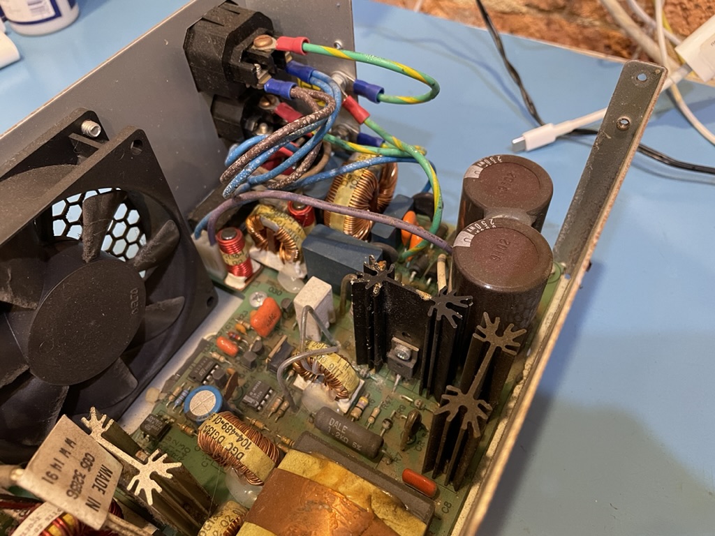
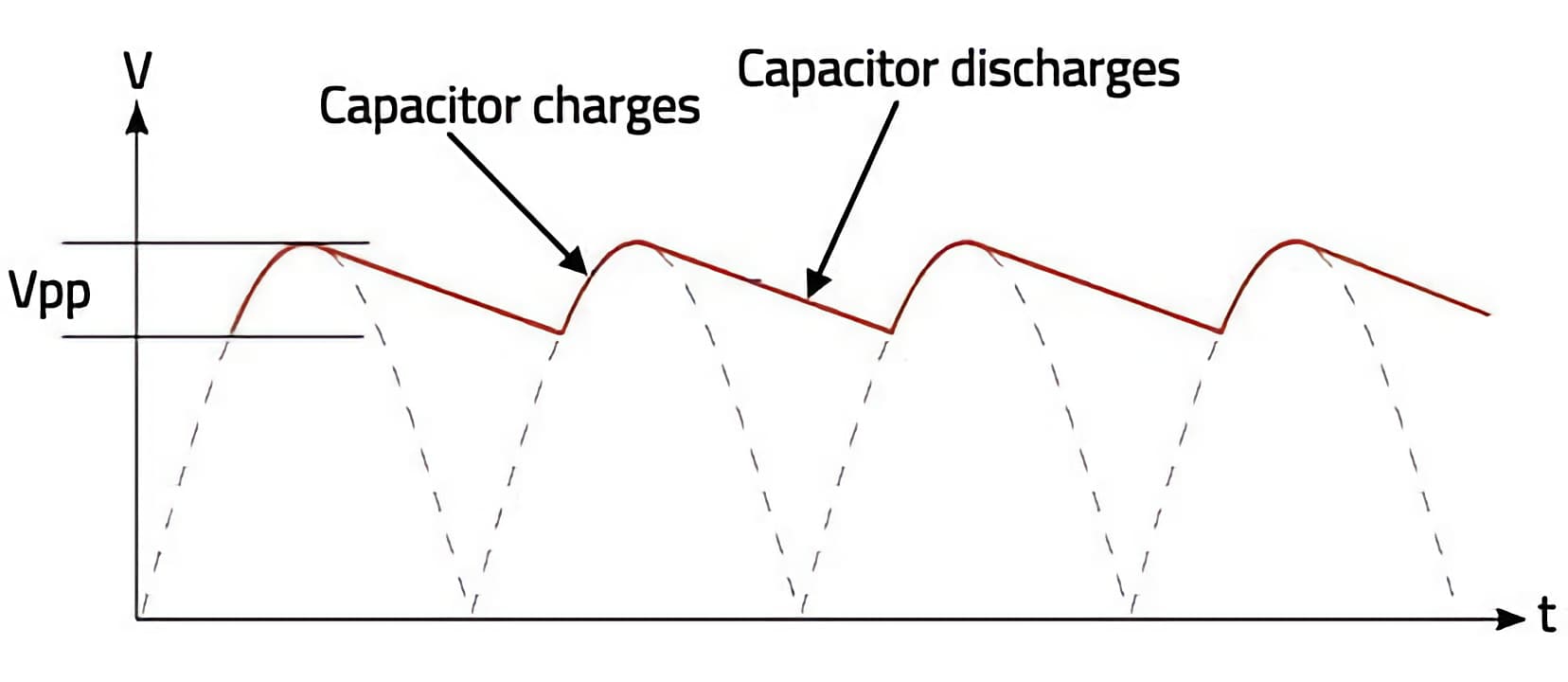
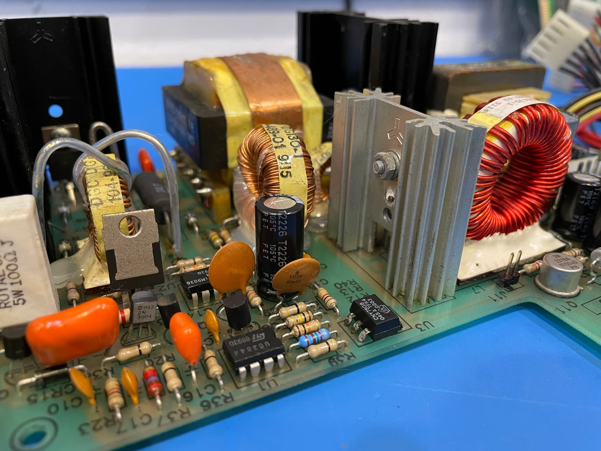
I’ve learned a thing or two while looking into this project. One of those is that in the power supply area, you want low ESR/high ripple current/low impedance capacitors. As I understand it, the oscillations of operating on AC can make components vibrate (or ripple) generating heat, capacitors are prone to this. This heat eventually will cause the ESR to increase as the capacitor electrolyte dries out. We reduce this in power supplies by using low ESR, high impedance with a high ripple current rating.

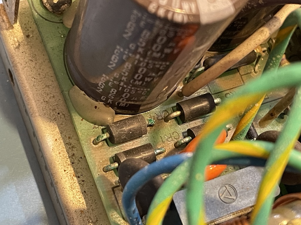
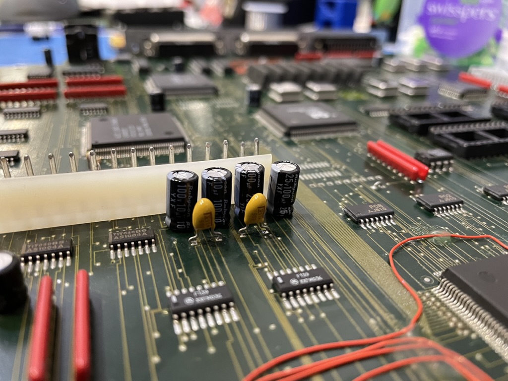
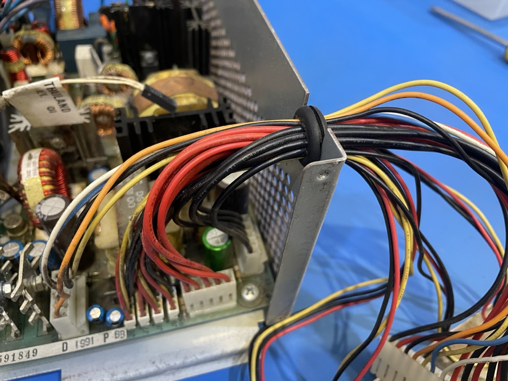
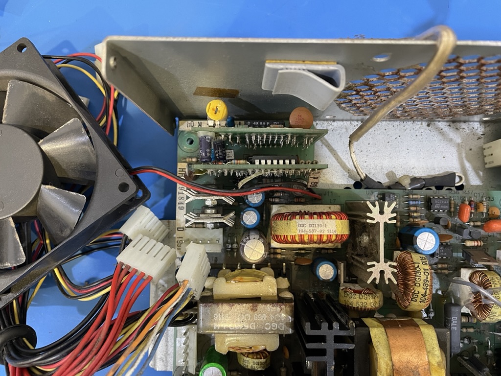
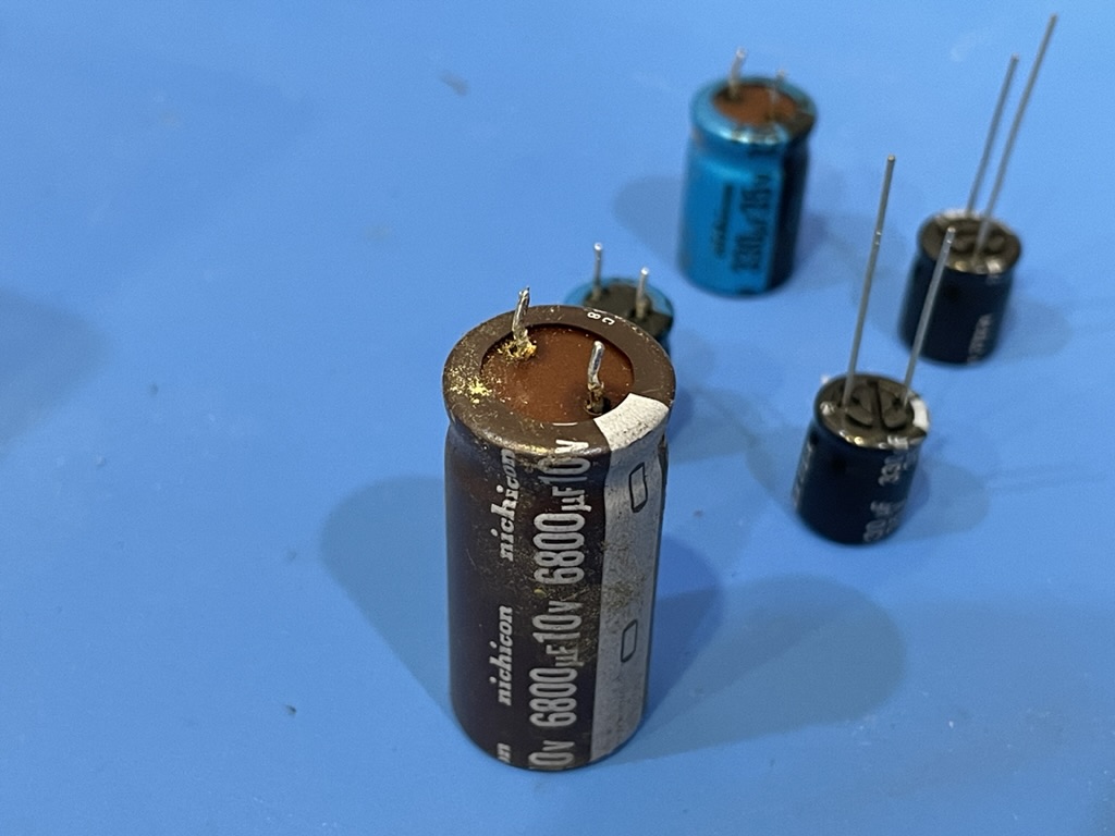
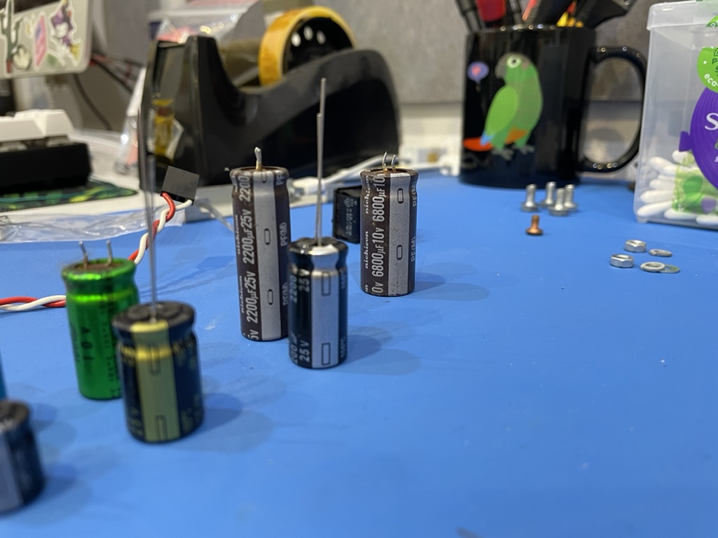
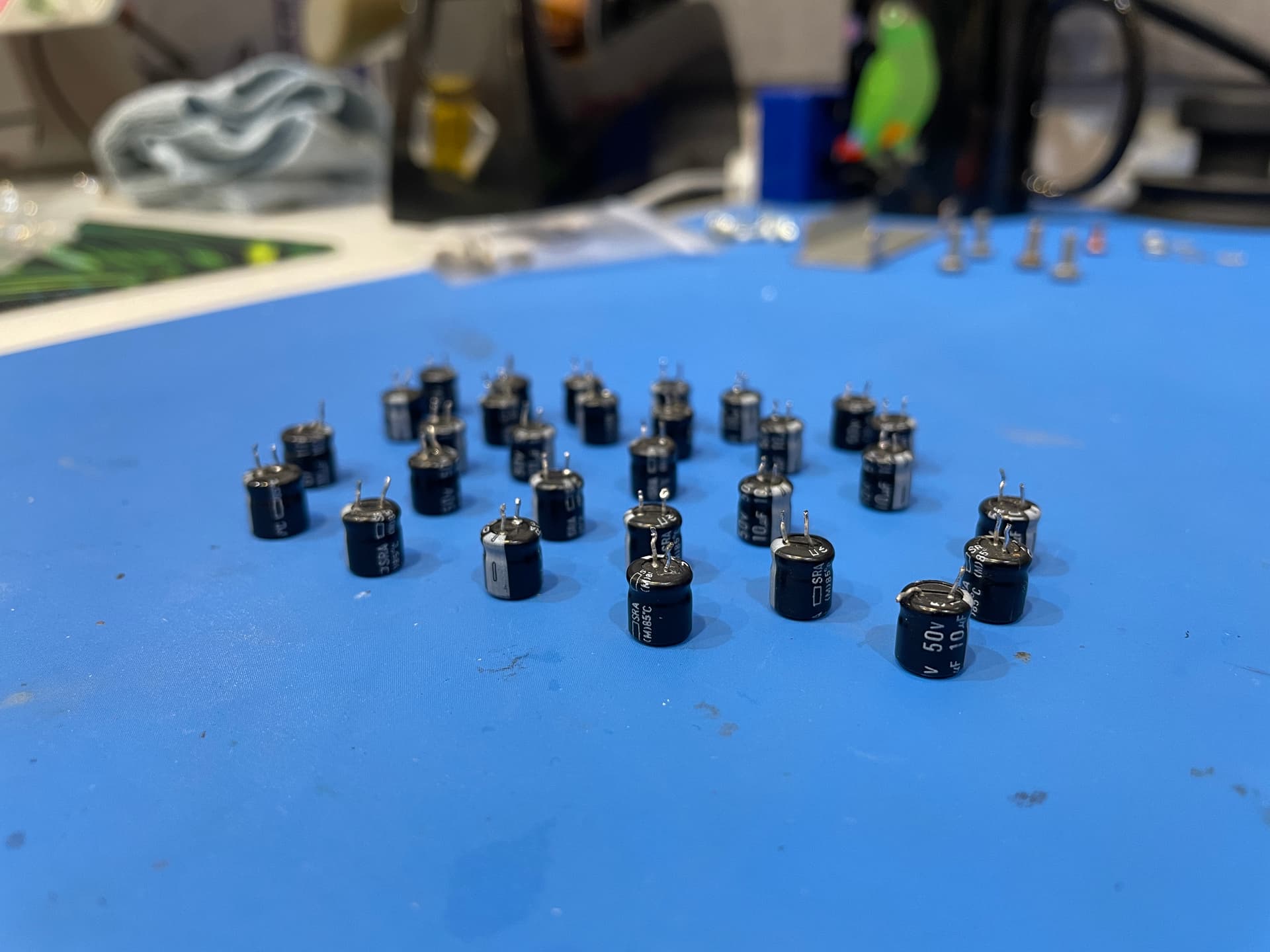
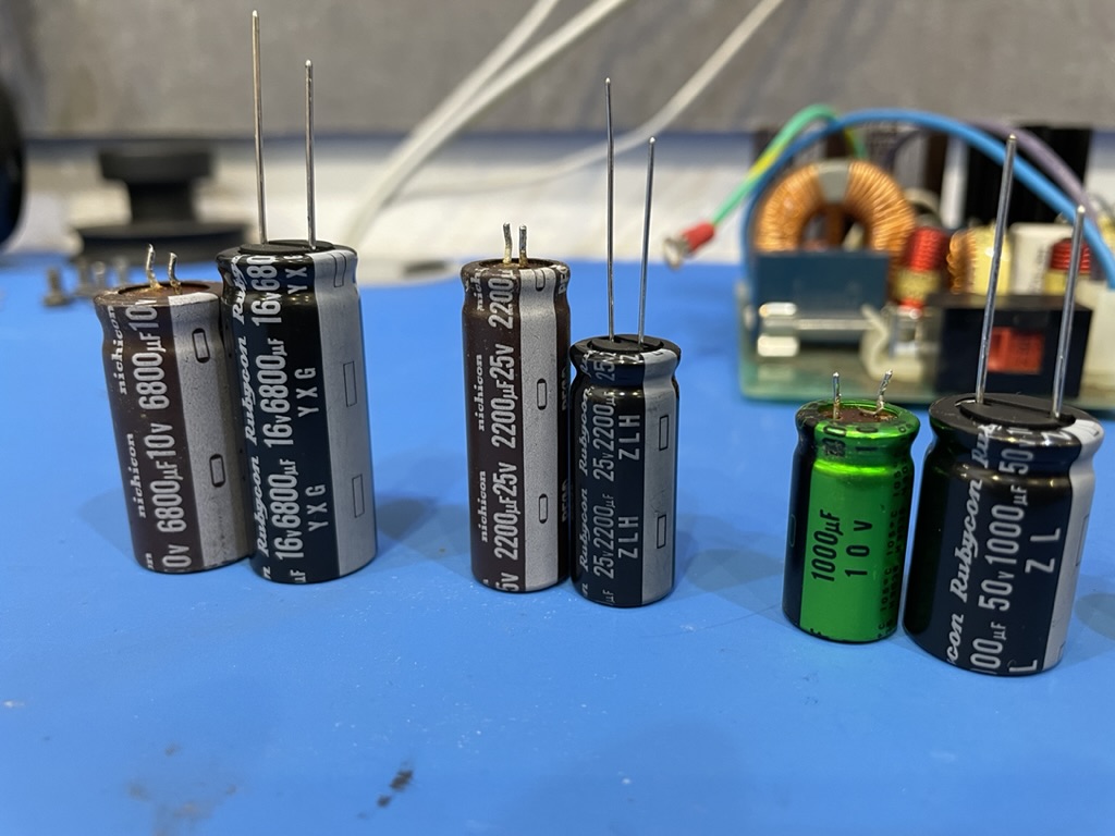
You can see the size difference in the originals compared to the potential replacements I decided against. With the excess ripple, it leads to a capacitor that will get hot, reducing lifespan.

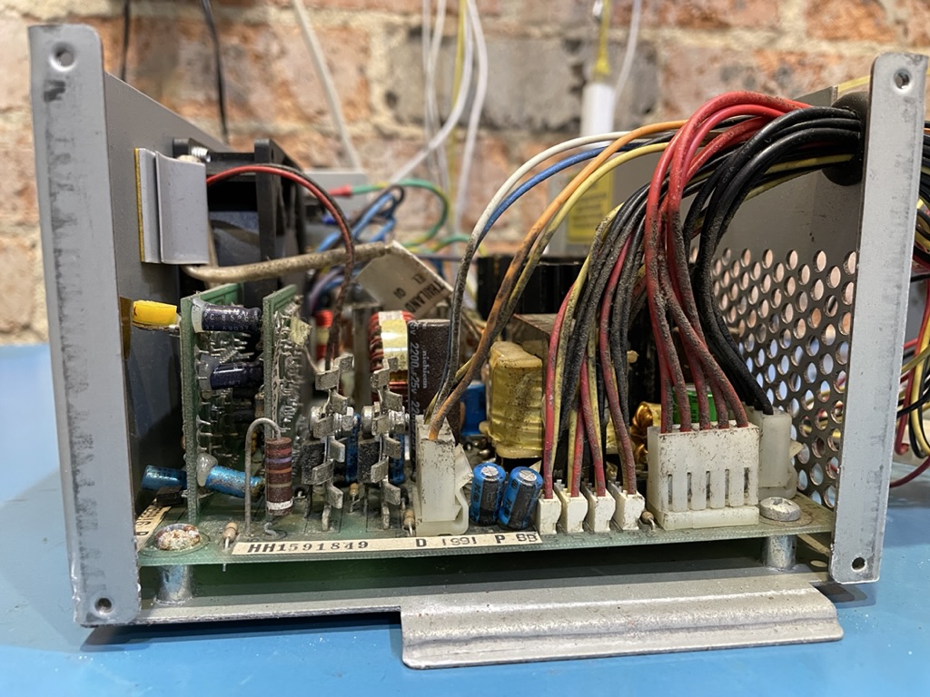
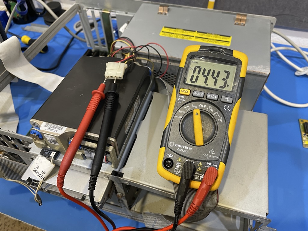
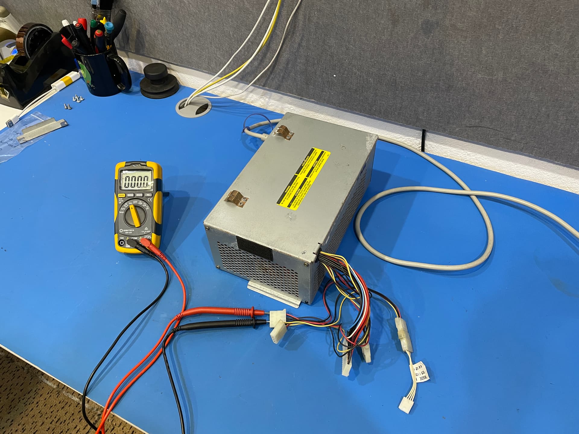
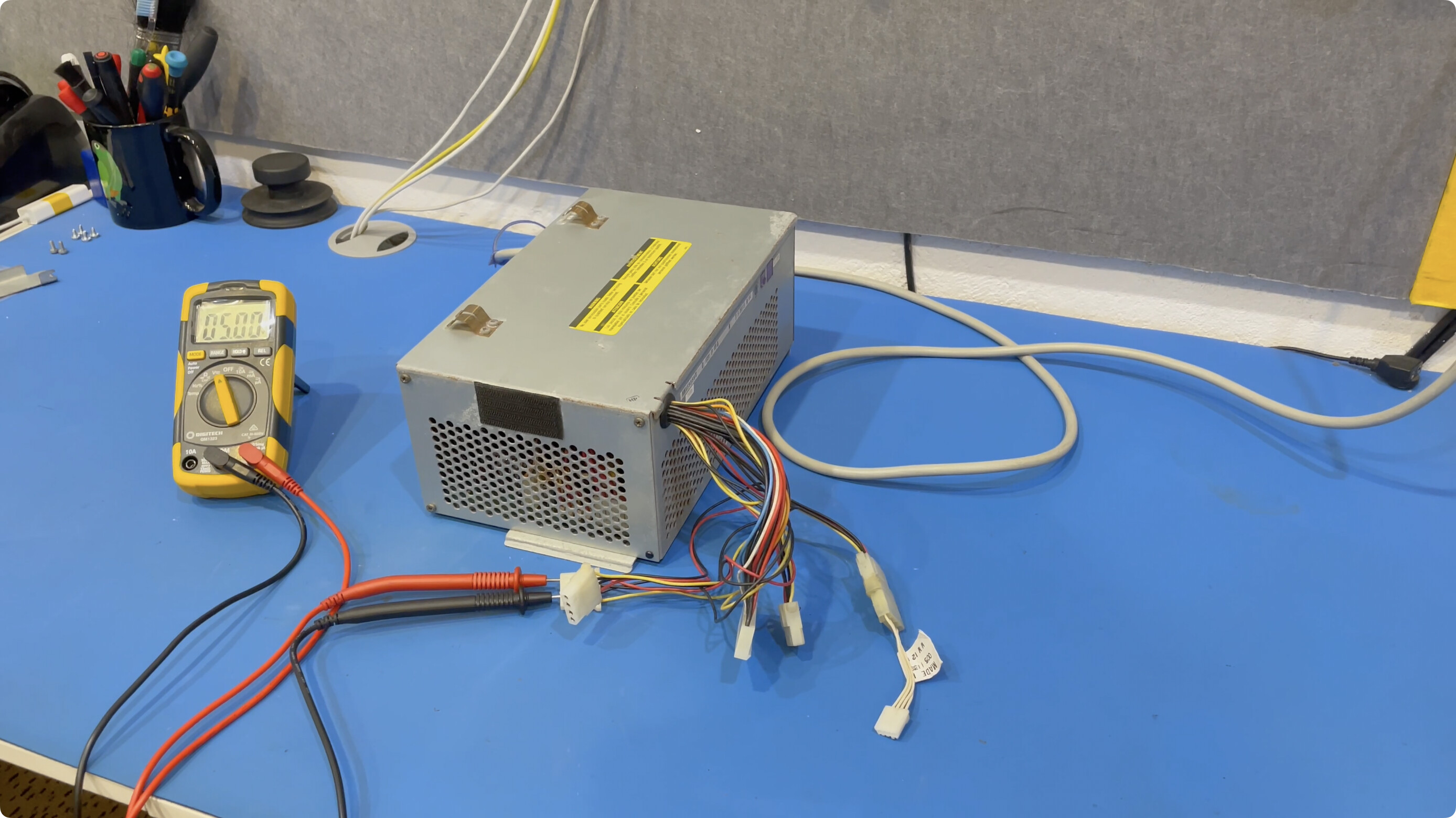
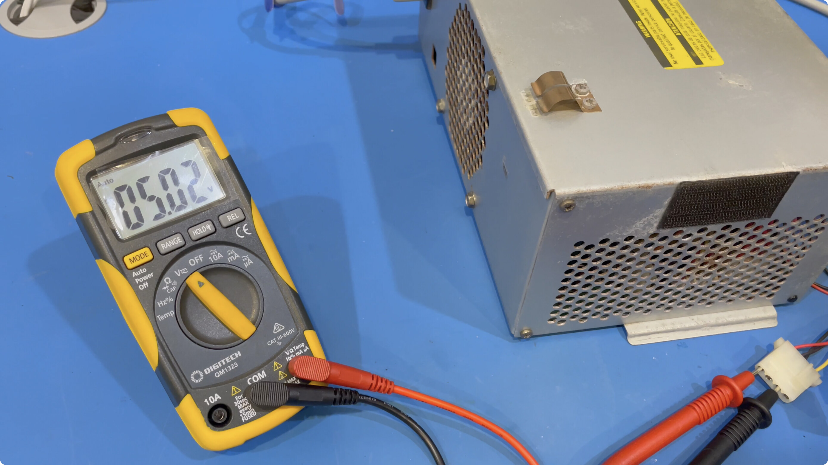
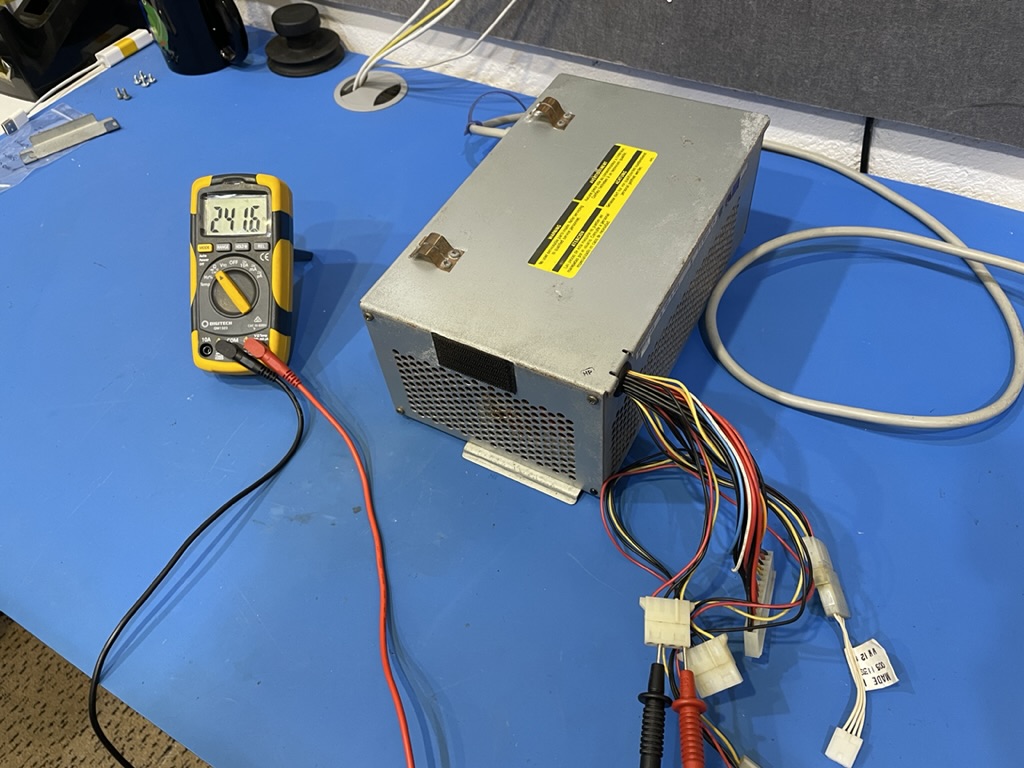
The theory we are working with on the no POST fault of this PC is that the capacitors in the power supply have an ESR that is too high. This allows noise to be introduced into the circuit. That noise is what I believe to be causing the power good signal to not be generated in time by the power supply - and probably that low +5V rail.

Remember we are only dealing with electrolytic capacitors in this project. We want to match, or exceed (see notes below) the old capacitors in at least these key areas when dealing with an AC mains power supply:

  • Capacitance
  • Voltage
  • Physical Size
  • Ripple Current Rating
  • Temperature

Capacitance
Match this with the value as close as you can. Most capacitors have a ±20% rating which may allow some movement in values but I have not had to ever change this. I would recommend that you don’t either.

Voltage
Increasing the voltage will increase the ripple current rating. Rubycon and Panasonic miniaturise their capacitors, often at the cost of the ripple current rating. Selecting a higher voltage will increase both the physical size and ripple current rating. This can be advantageous when working on older hardware as your capacitors will fit better.

Physical Size
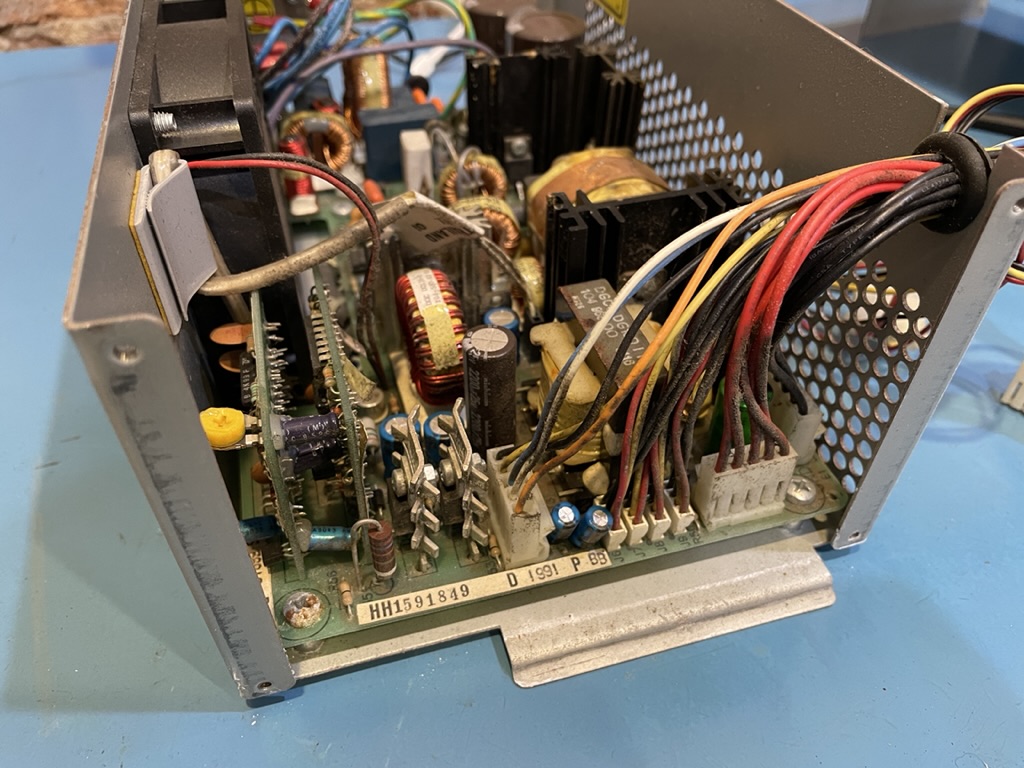
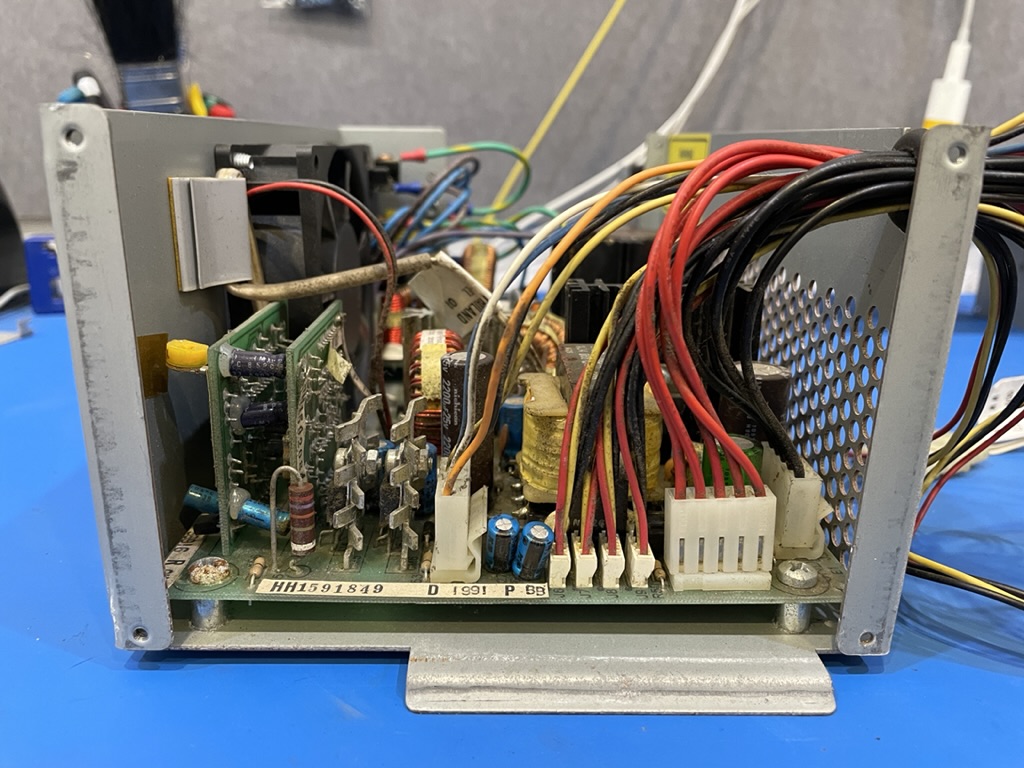
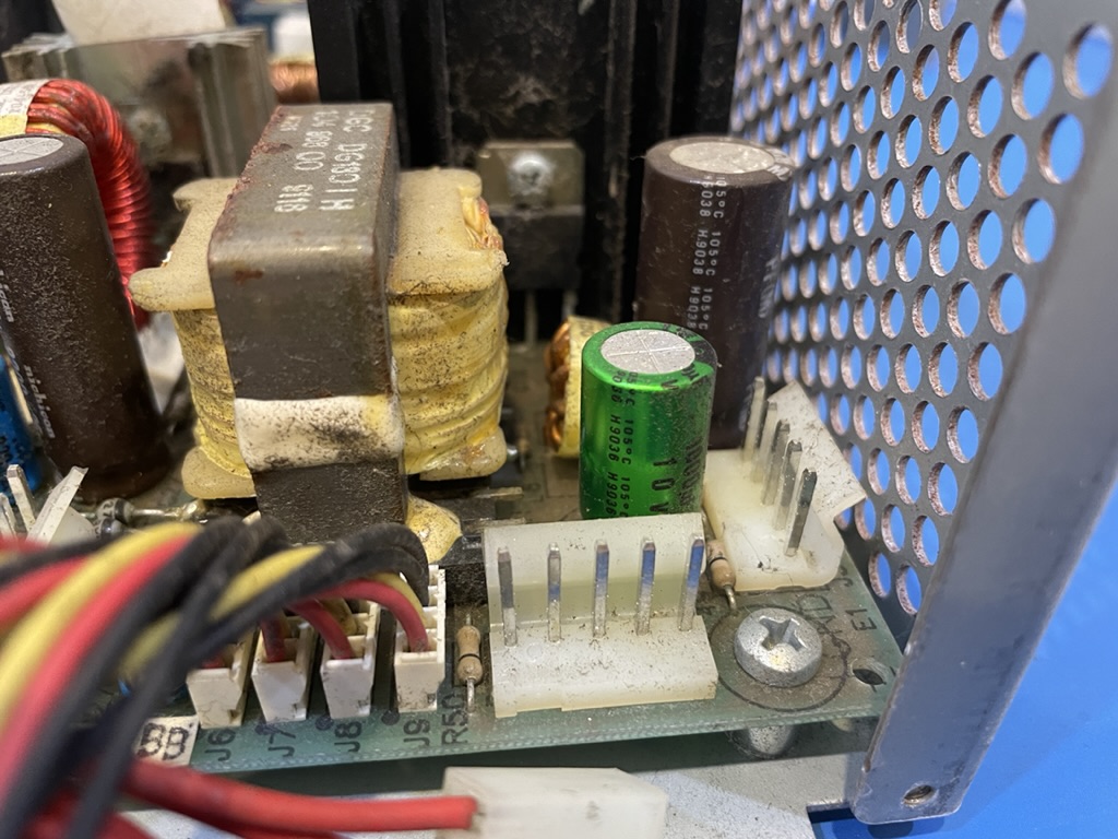
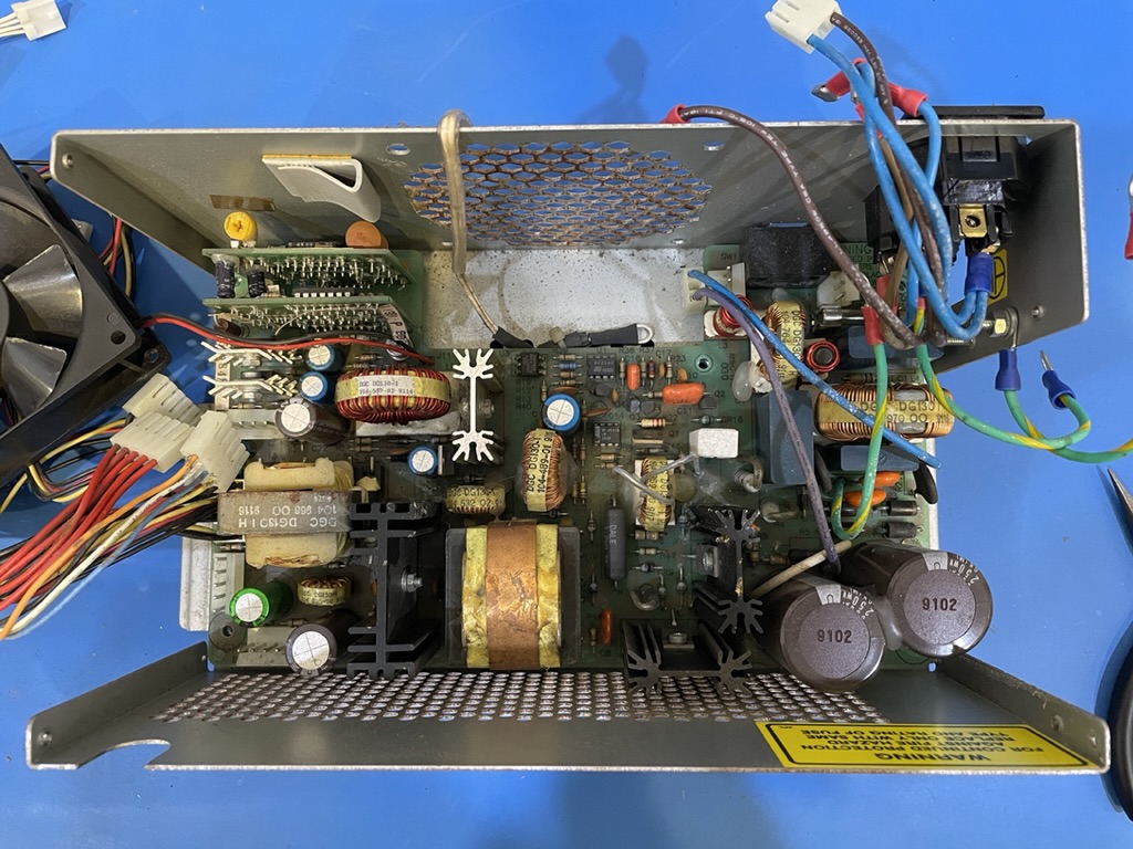
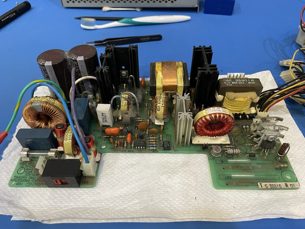
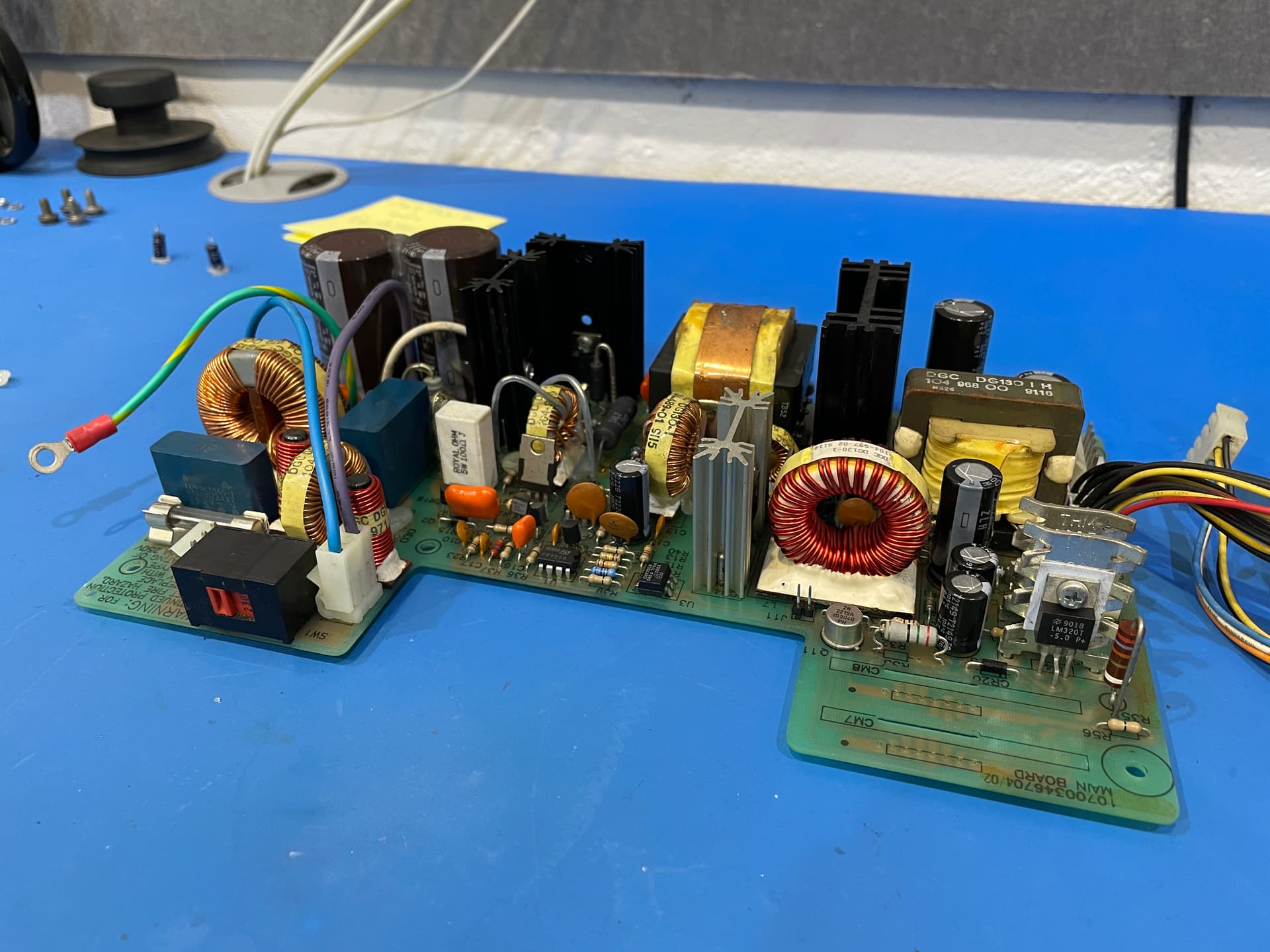
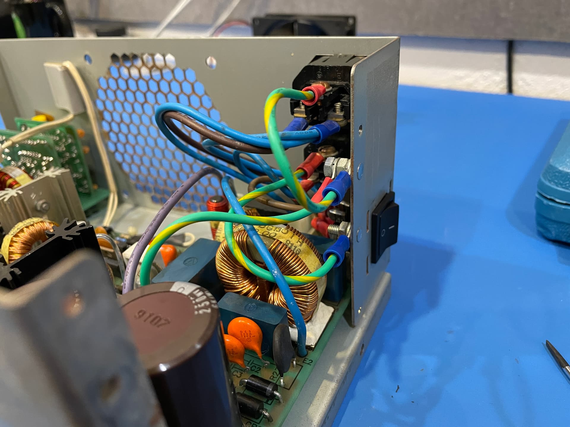
Keep an eye on the clearance, for example this power supply has plenty of height but not much width for the capacitors. The lead (leg) spacing on the capacitors should also be matched where possible.

Ripple Current Rating / ESR
Keep the ripple current rating as high as possible and ESR as low as possible. The two usually go hand-in-hand. Always check the datasheet and compare between brands. Low ESR/high ripple capacitors are usually more expensive, but picking from general-use capacitors will result in a hot running capacitor with shortened life span. Even worse, it’ll probably be operating out of range when compared to the circuit designers specifications.

Anyone with more on the physics is welcome to chime in, especially since I’m a botanist by trade :potted_plant:

Temperature
You should always keep this the same or higher than the capacitors you are replacing.

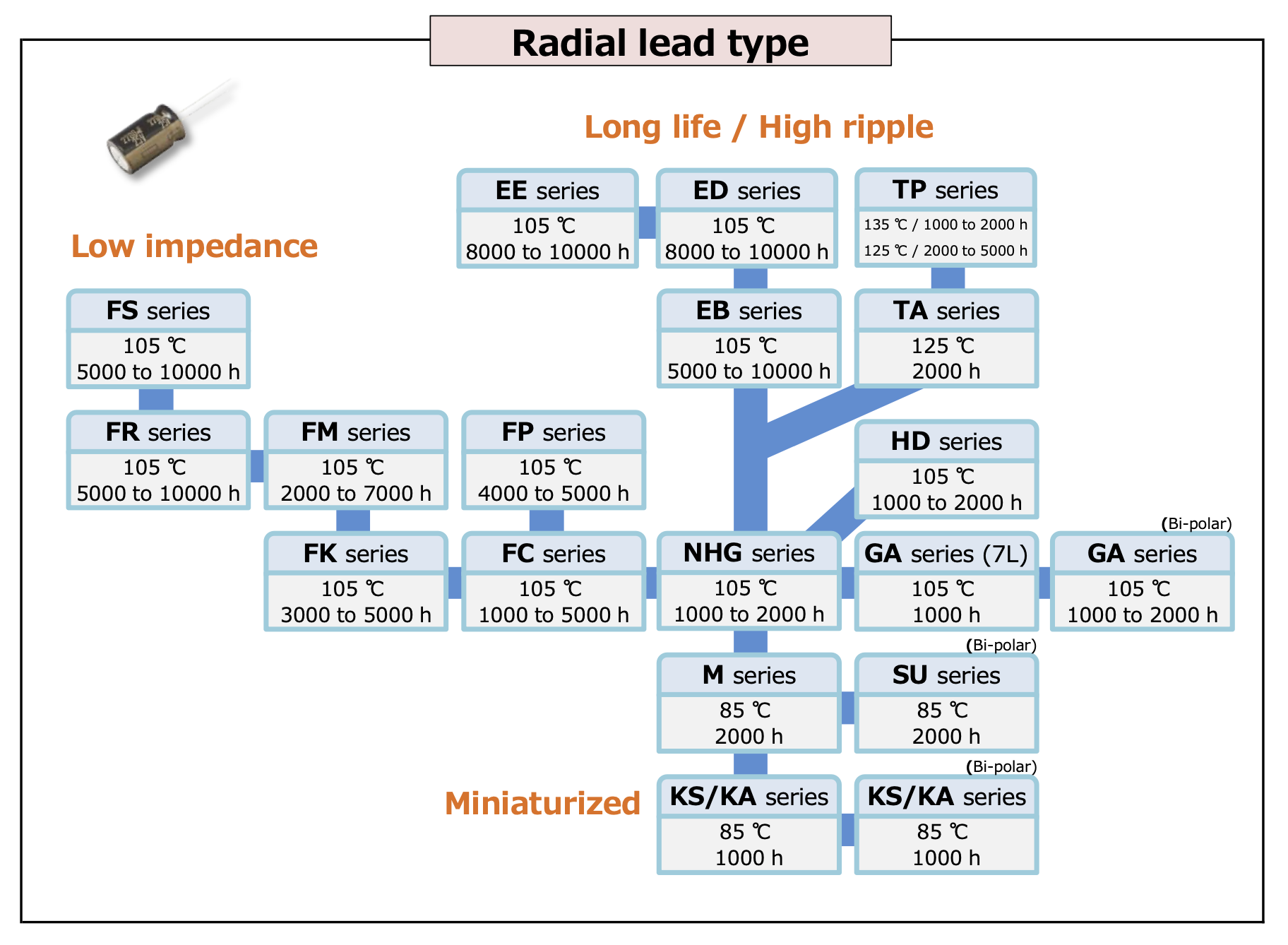
Here is a screen cap of Panasonic’s capacitor flow chart. For this project I would probably want to use capacitors in the FM, FR or FS series. I’ve gone the Rubycon route though, so we’ll have a look at their flow chart.

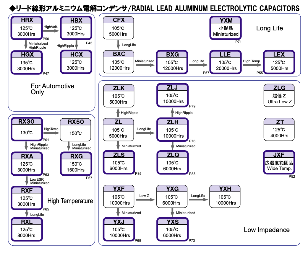
The lower right quadrant is where our interests lie, the low impedance area. Remembering we are in the middle of a capacitor shortage, let’s look at what I’ve ordered and any notes:

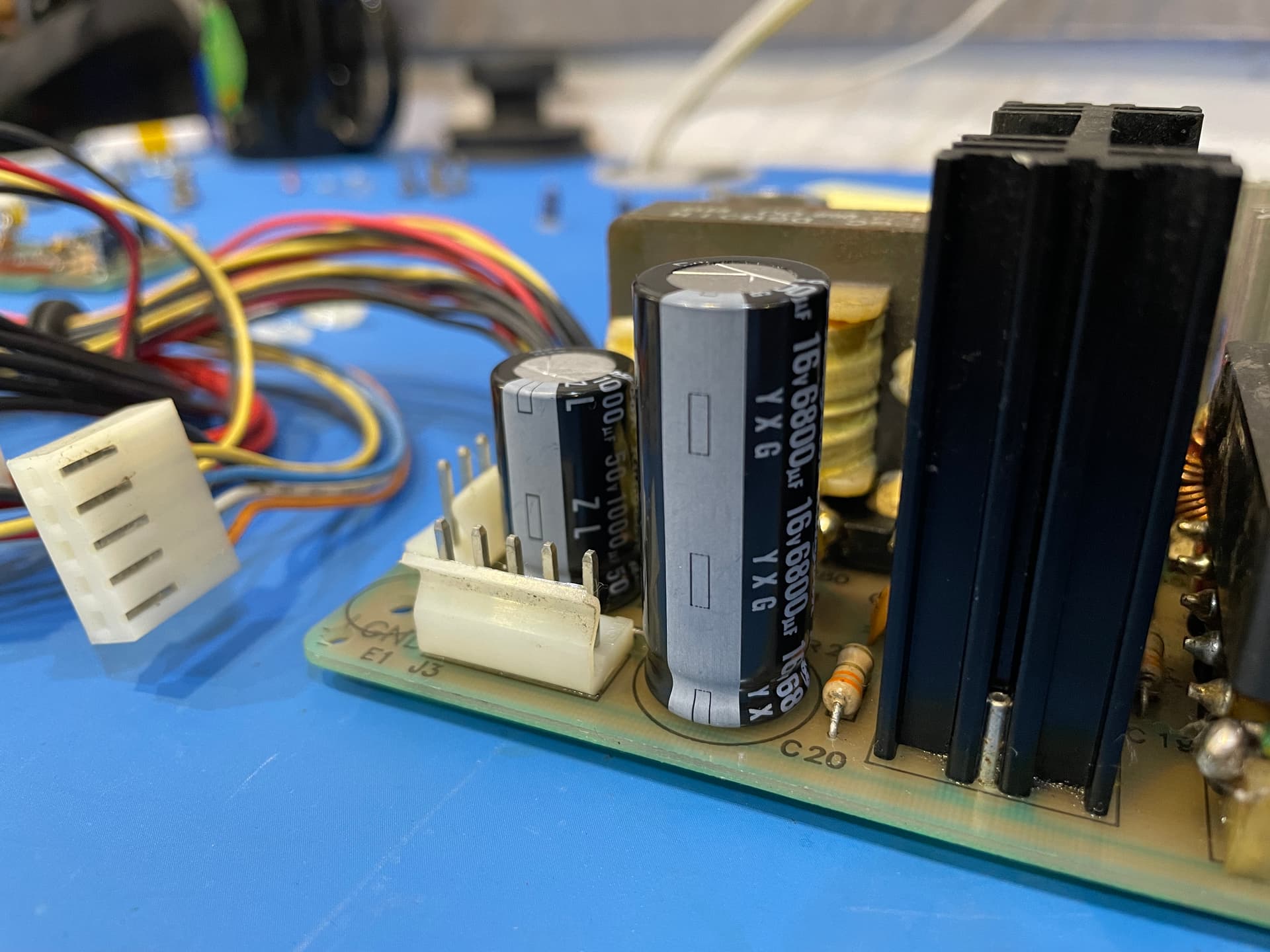
6800uF - Rubycon YXG Series
Low impedance
10V to 16V upgrade
5mm taller, plenty of clearance in the PSU case

2200uF - Rubycon ZLH Series
Miniaturised, long life, low impedance
Specs are the same - no changes

1000uF - Rubycon ZL Series
High ripple current, low impedance
Lead spacing from 5mm to 7.5mm
Width from 12mm to 16mm
10V to 50V upgrade

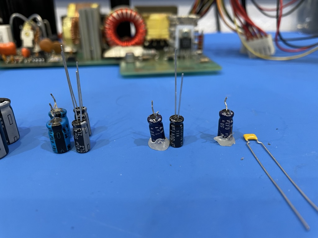
330uF - Rubycon ZLJ Series
High ripple current, long life, low impedance
35V to 50V and a 10V to 50V upgrade
Taller but plenty of clearance

220uF - Rubycon ZLJ Series
High ripple current, long life, low impedance
25V to 50V upgrade

47uF - Rubycon ZLJ Series
High ripple current, long life, low impedance
Leg size 2mm - will need to bend to fit 5mm lead spacing
Width reduction - 6mm to 5mm
16V to 35V upgrade

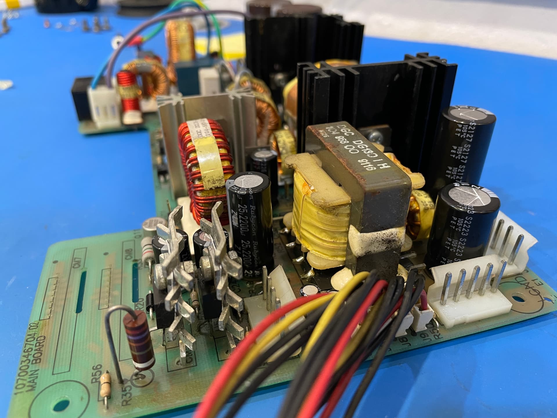
Now some of these upgrades are fairly big jumps for the voltages, it goes to show how far capacitor tech has advanced when you get some of the more reputable brands. You can see the recurrence of low impedance and high ripple current on most of the capacitors though. For reference, we’re mostly pulling out Nichicons and they are well past their service life.

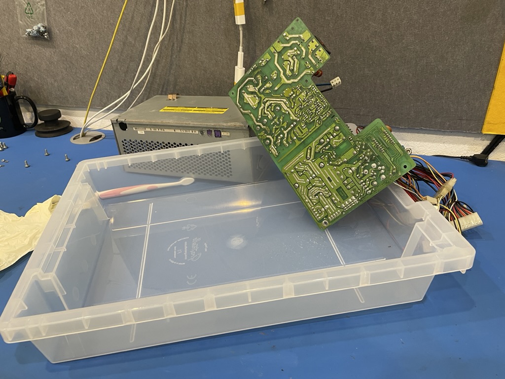
For now, we wait for the capacitors to arrive, they should be here by next weekend. In the meanwhile I’ll be:

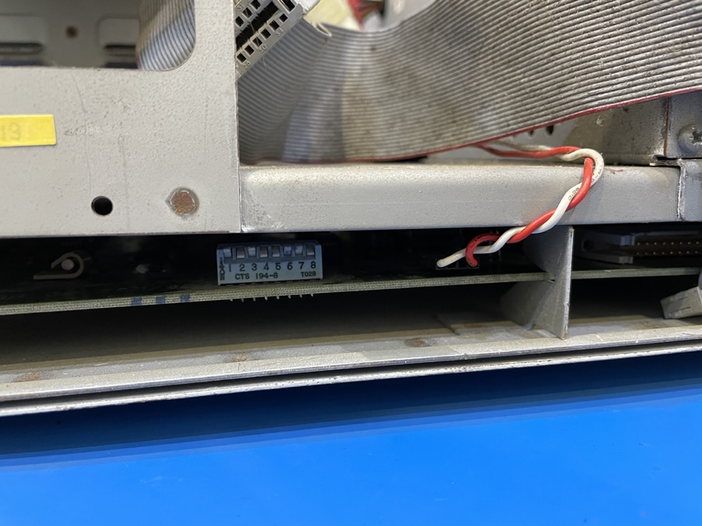
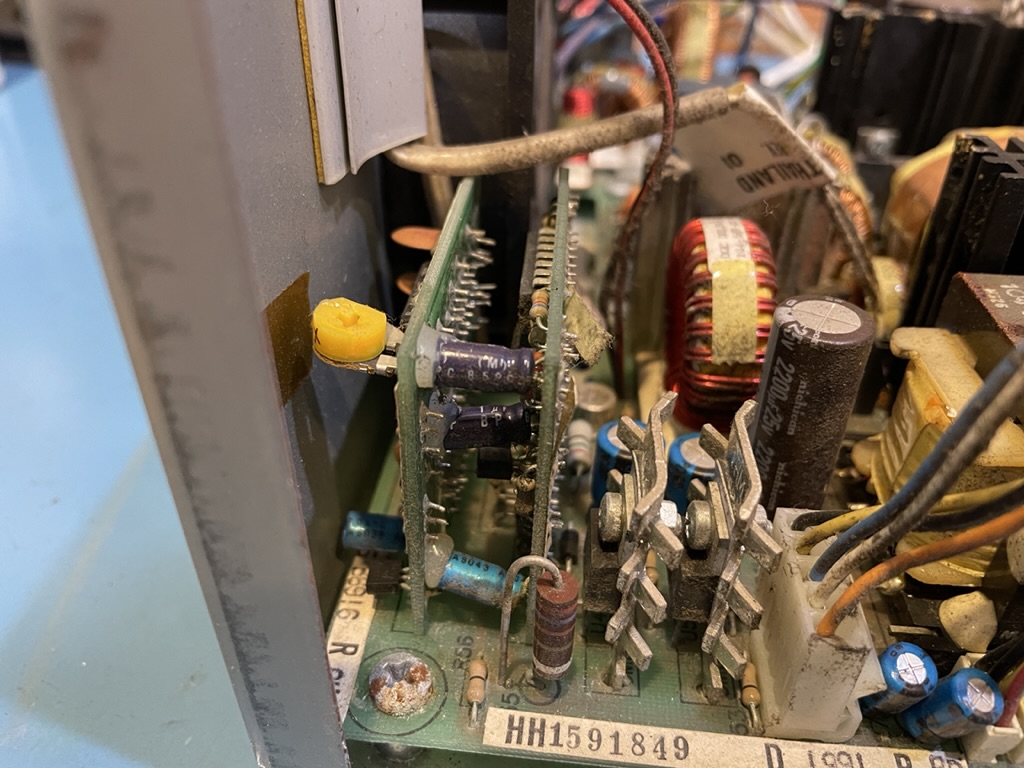
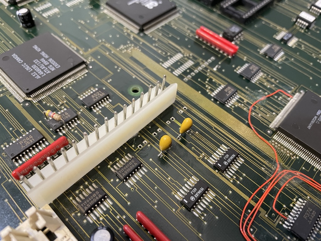
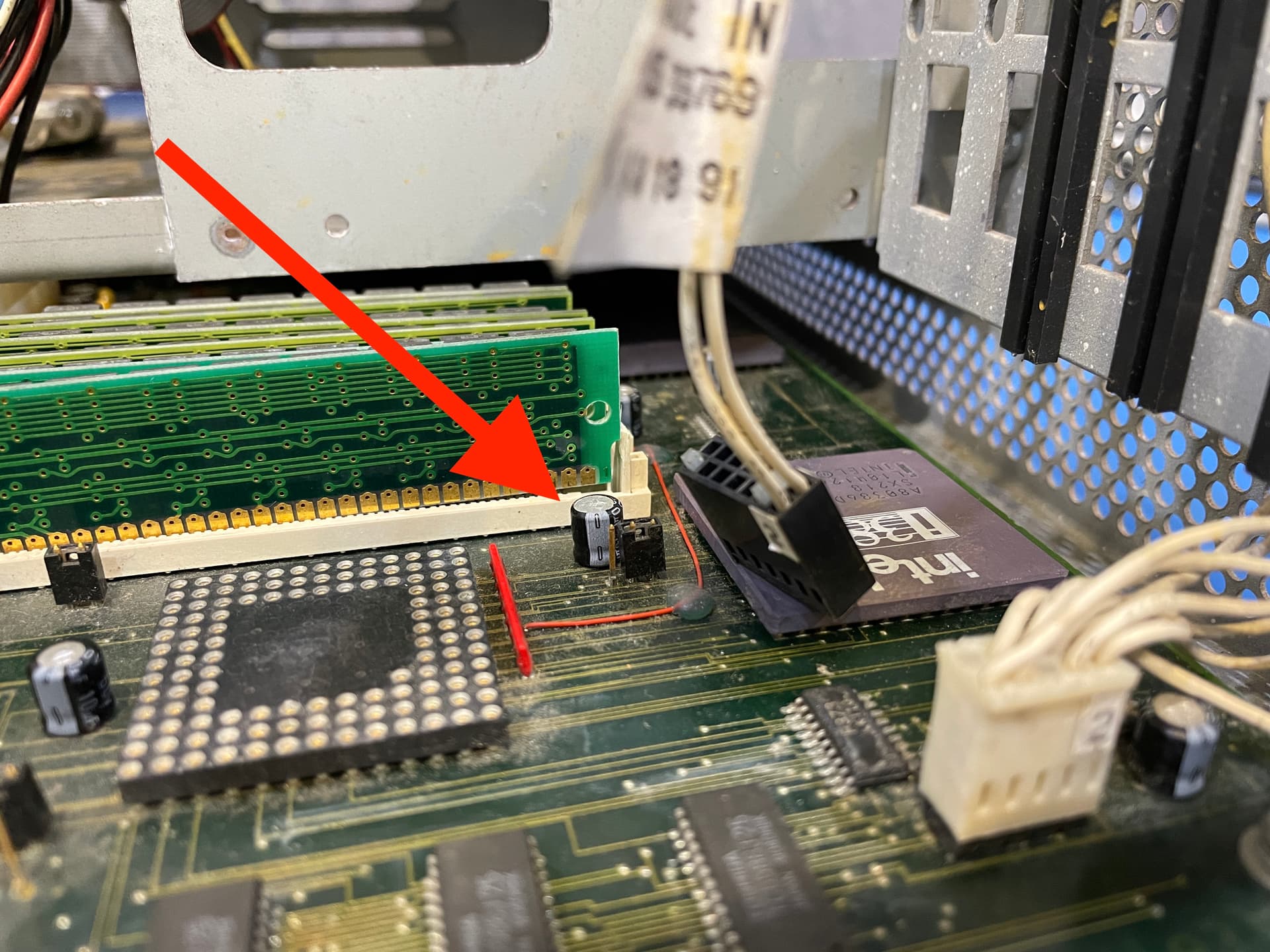
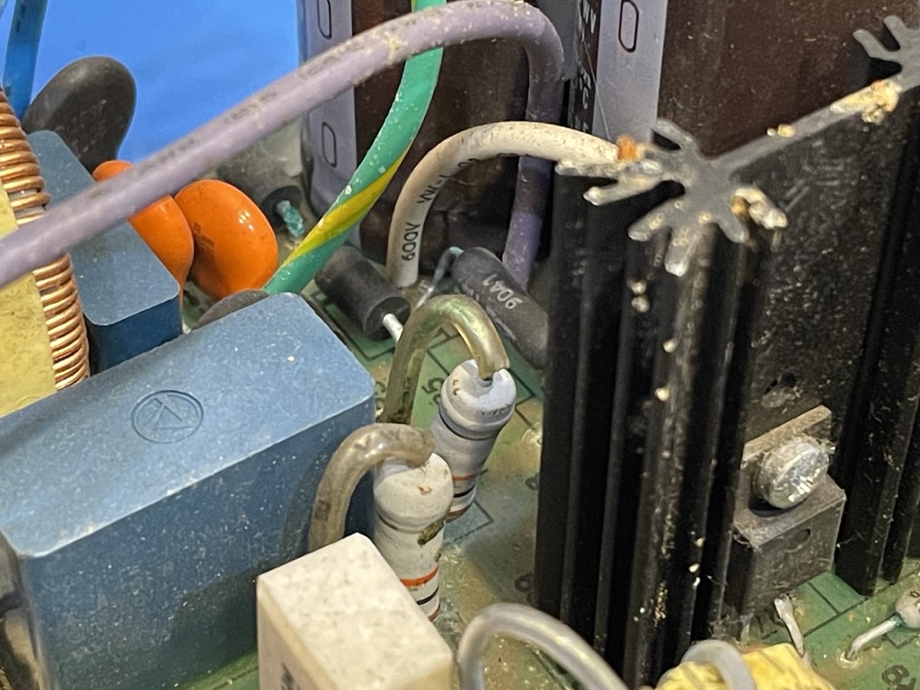
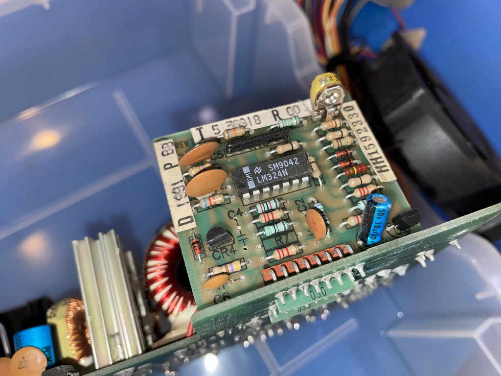
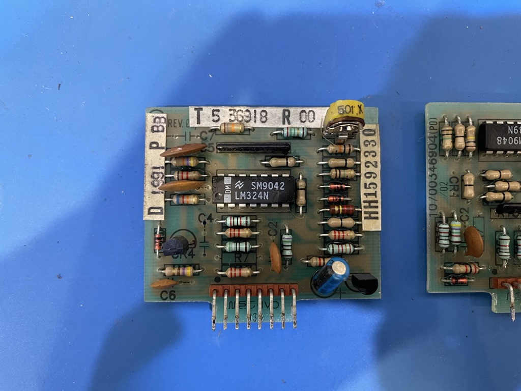
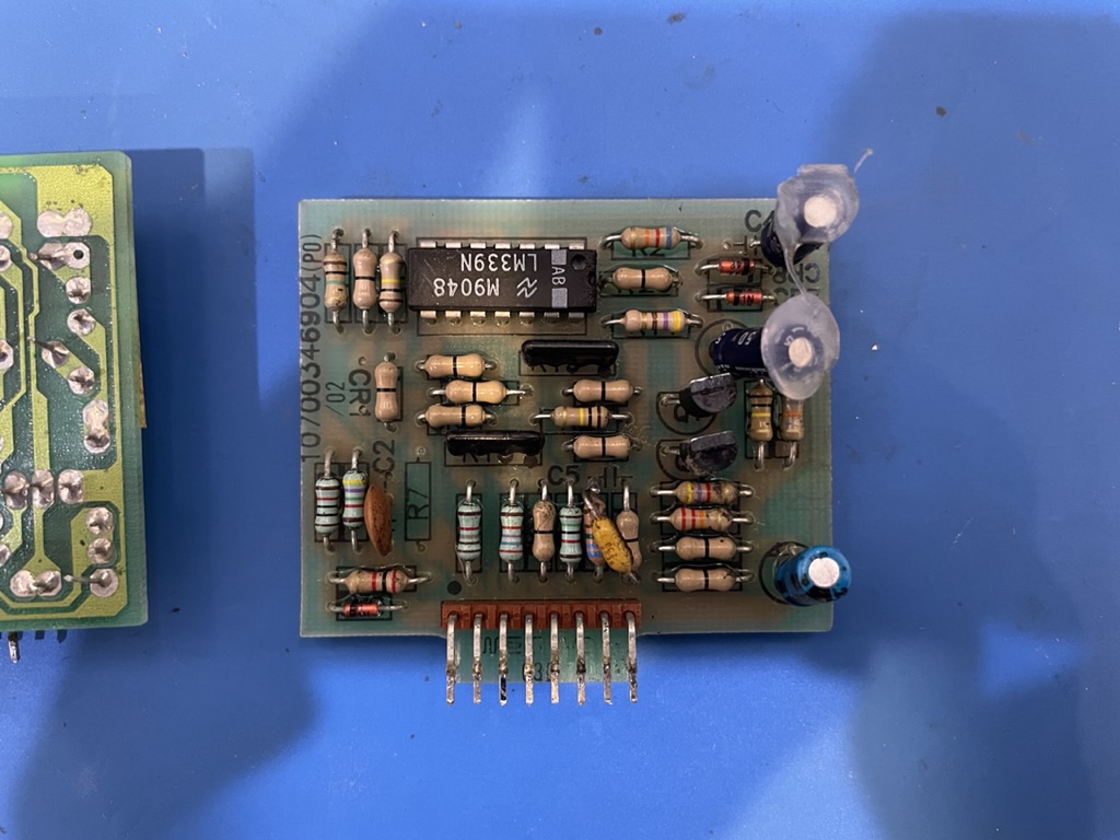
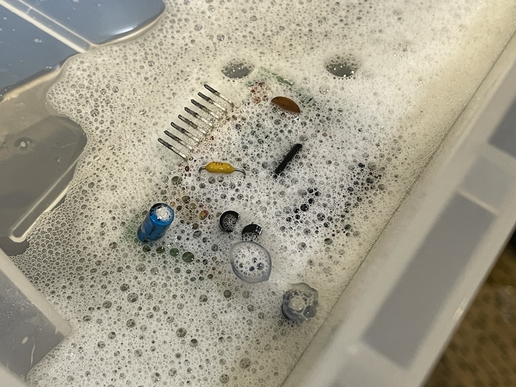
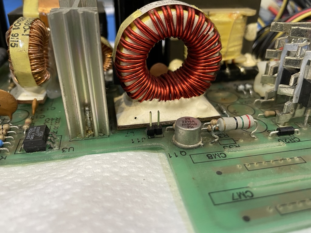
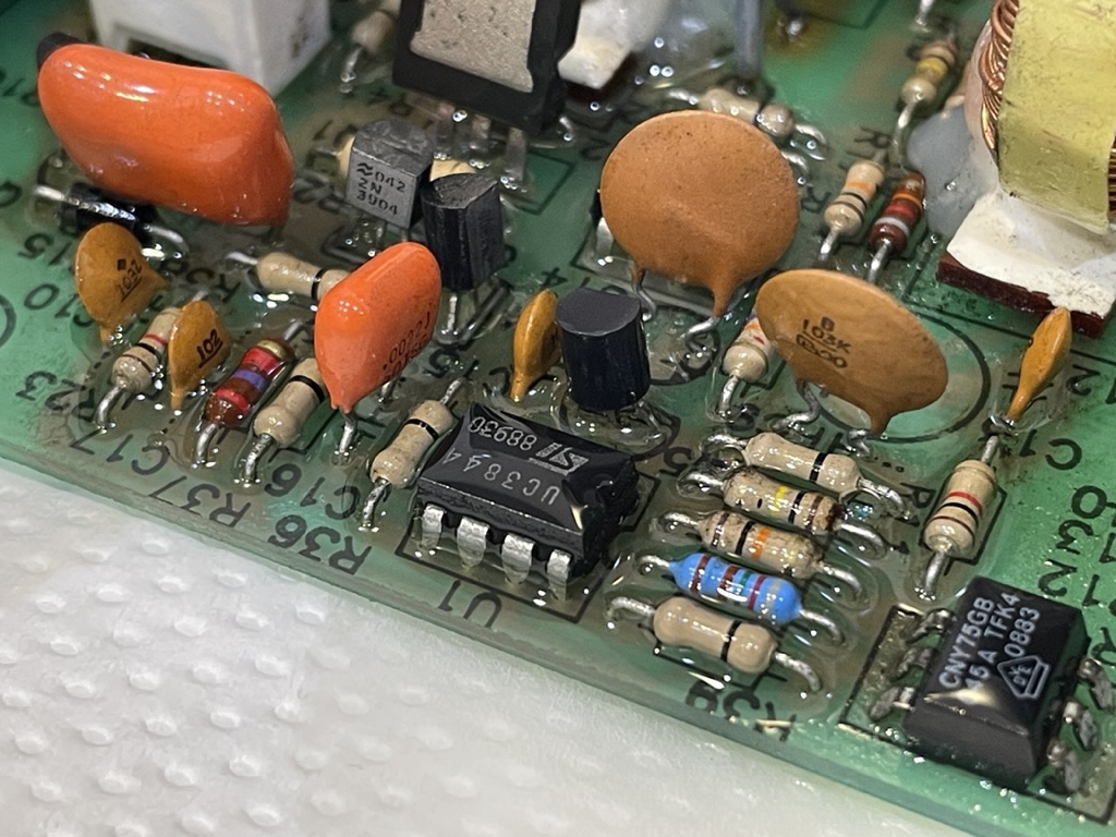
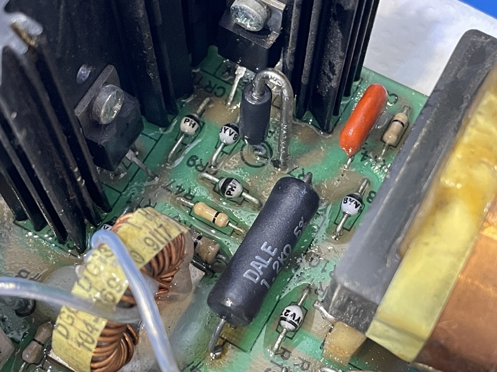
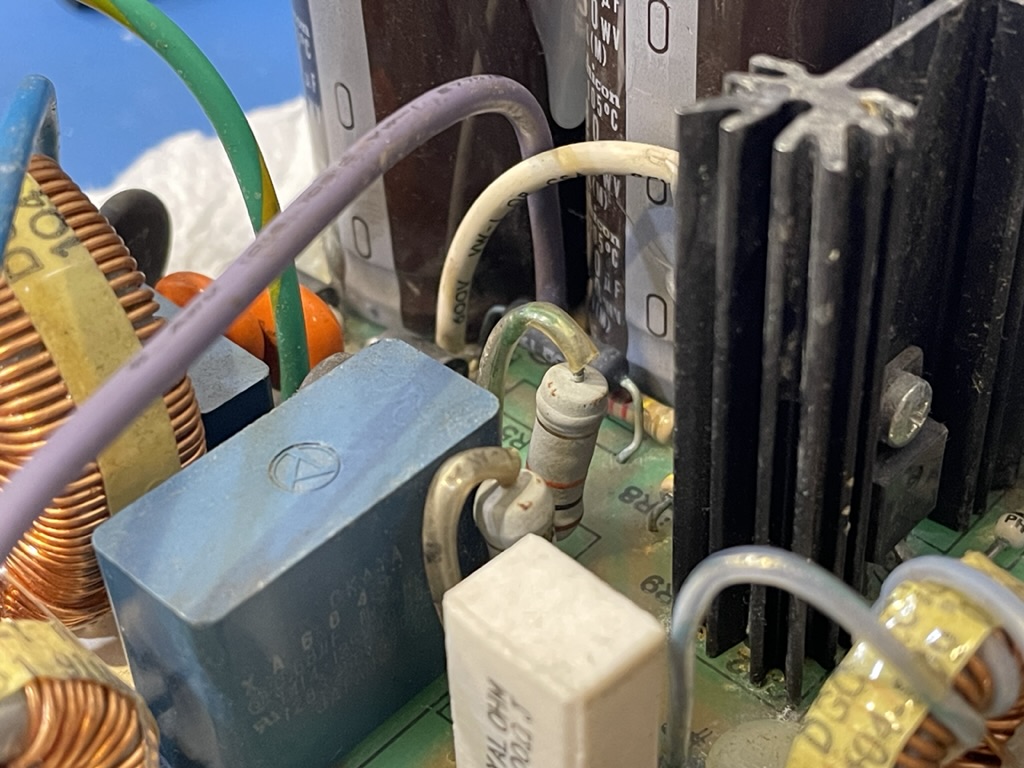
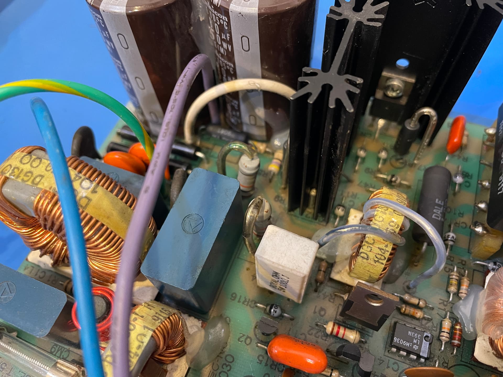
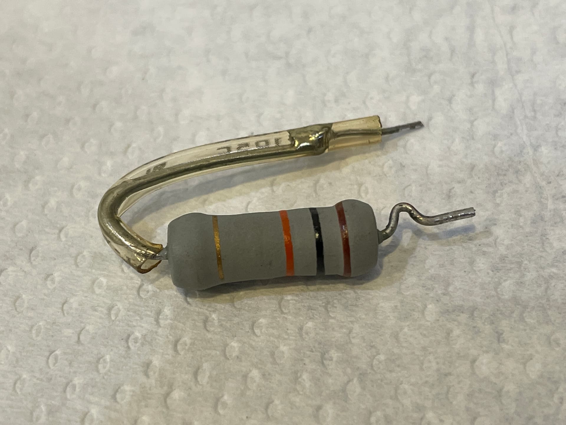
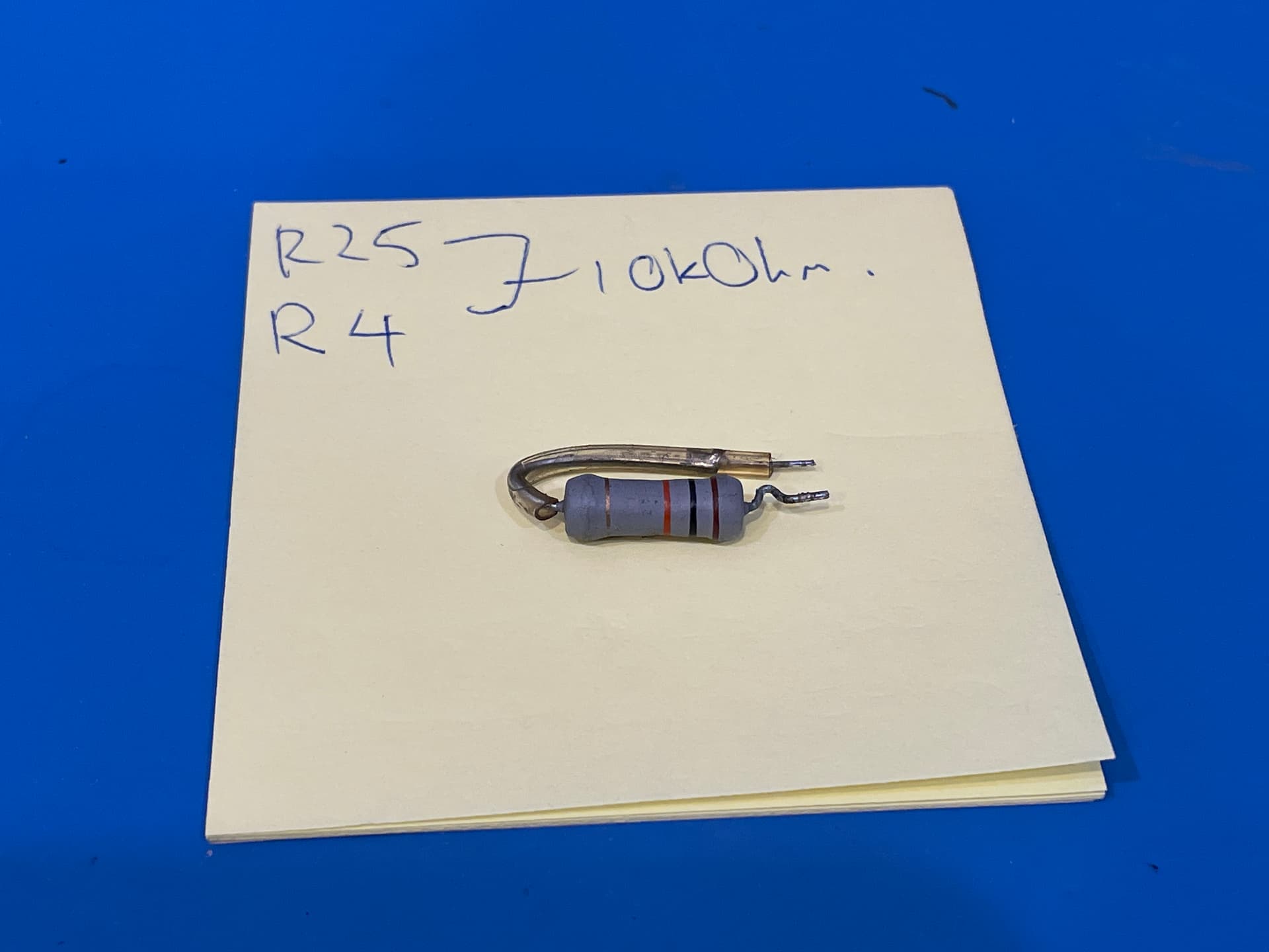
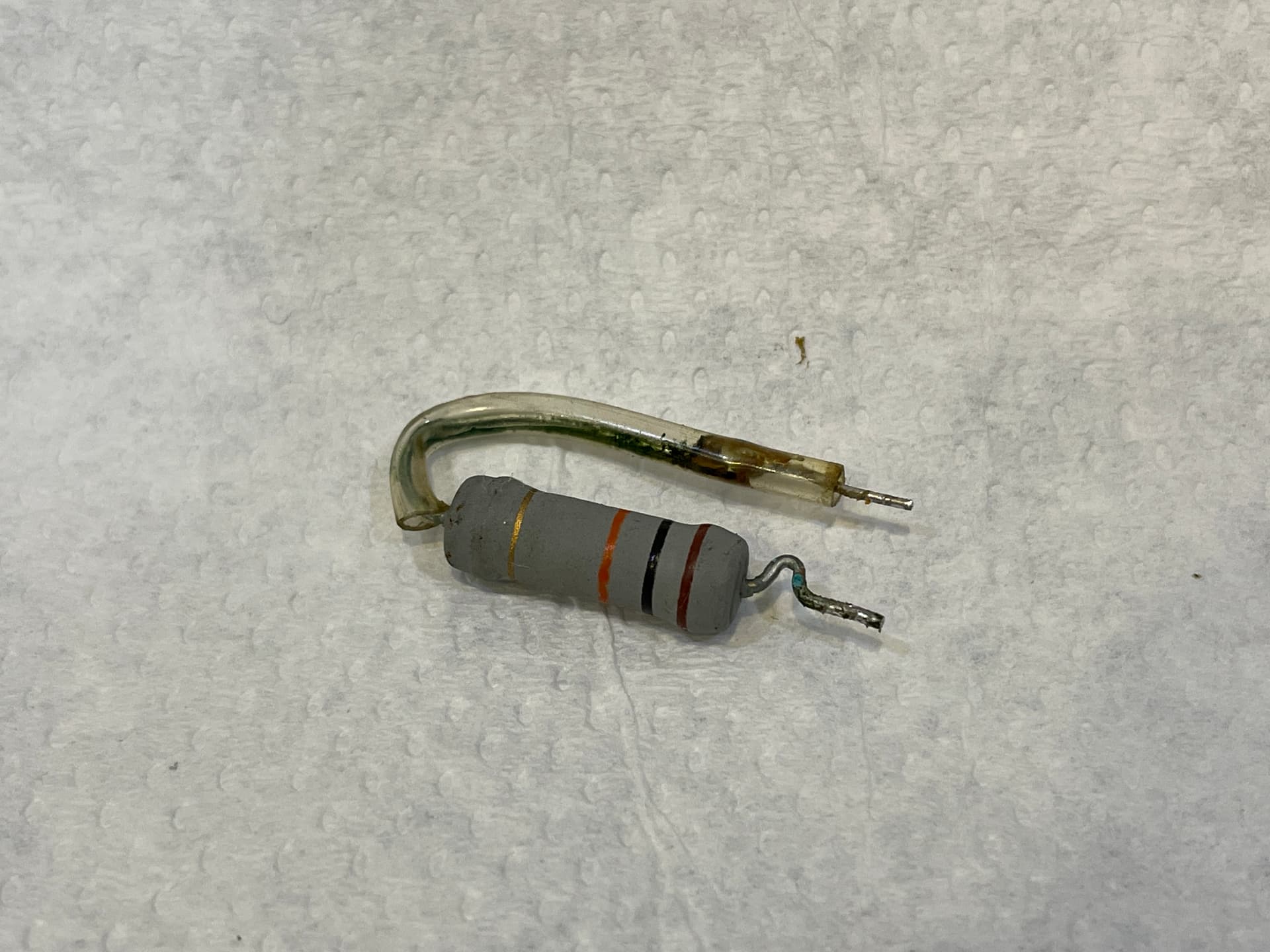
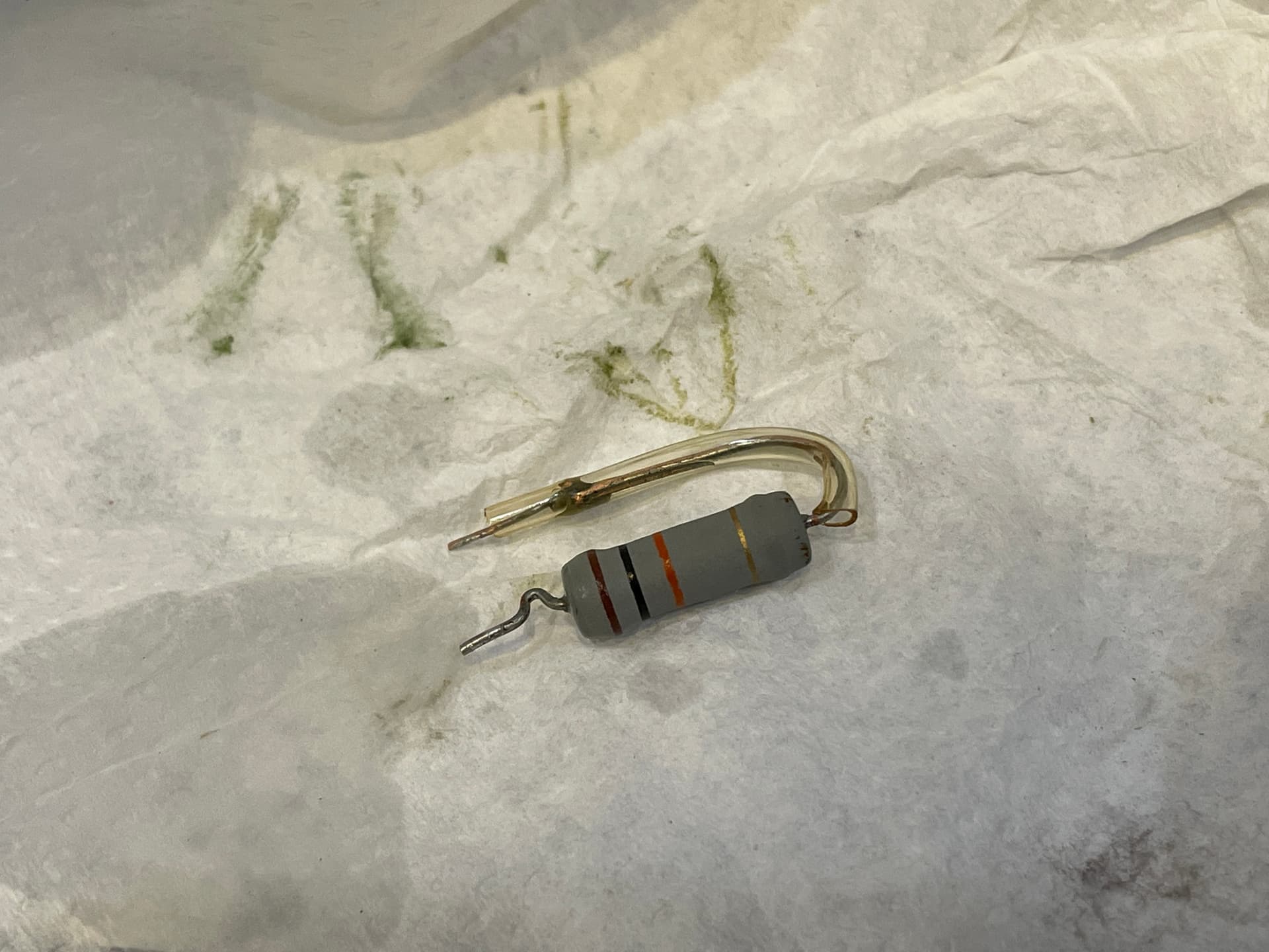
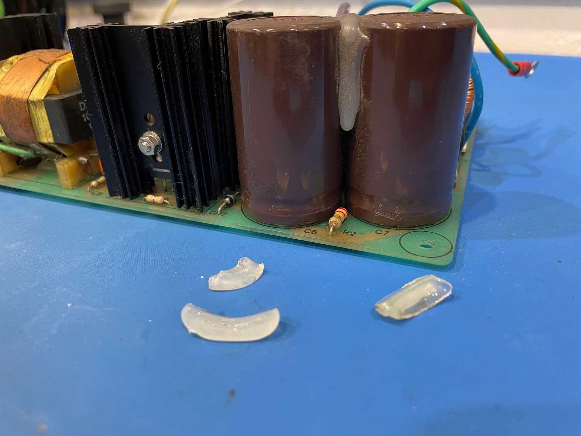
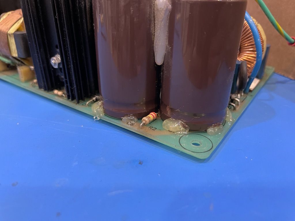
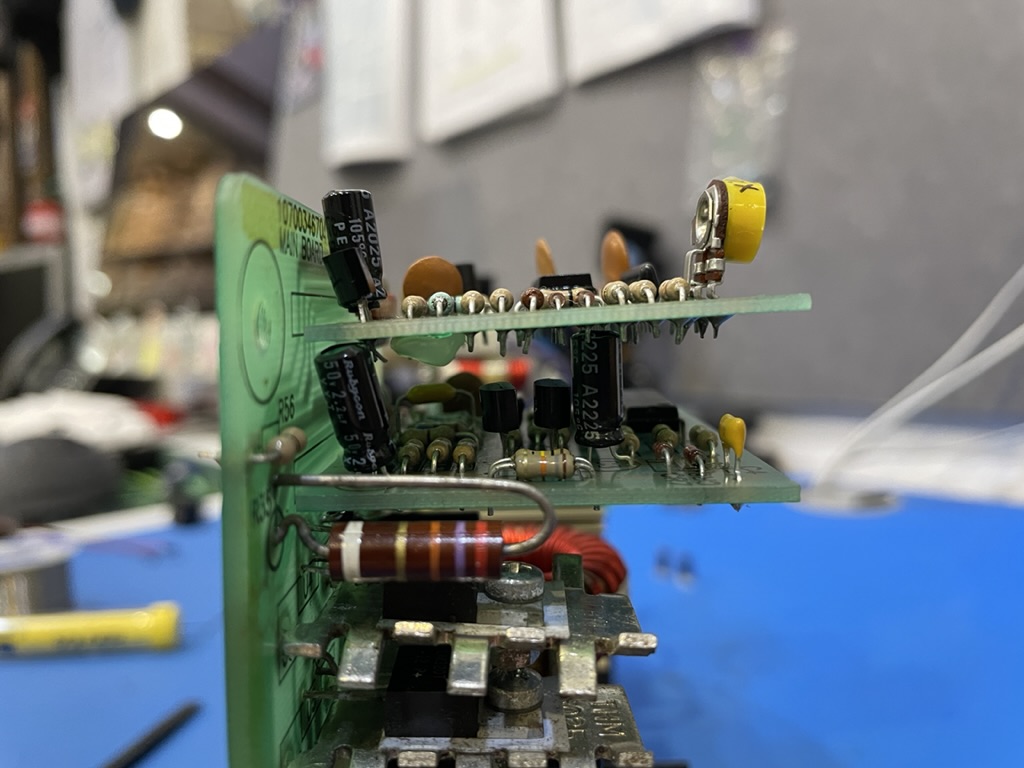
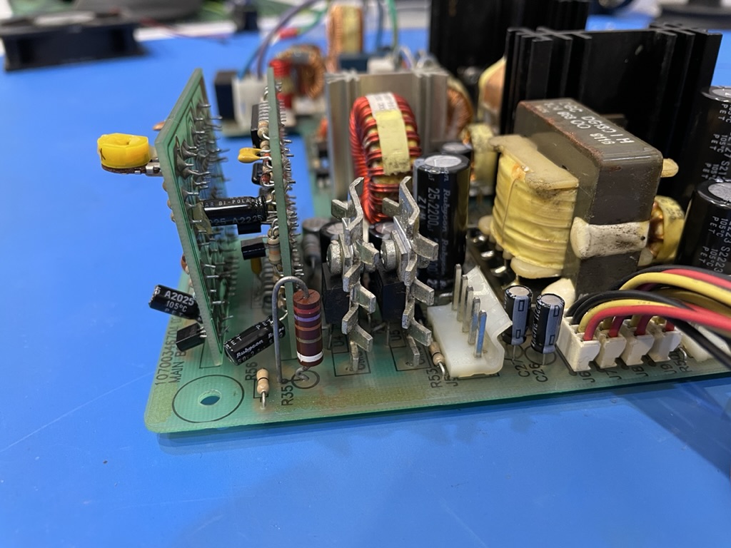
  • Removing the resistors pictured above and cleaning inside the plastic protective tube.
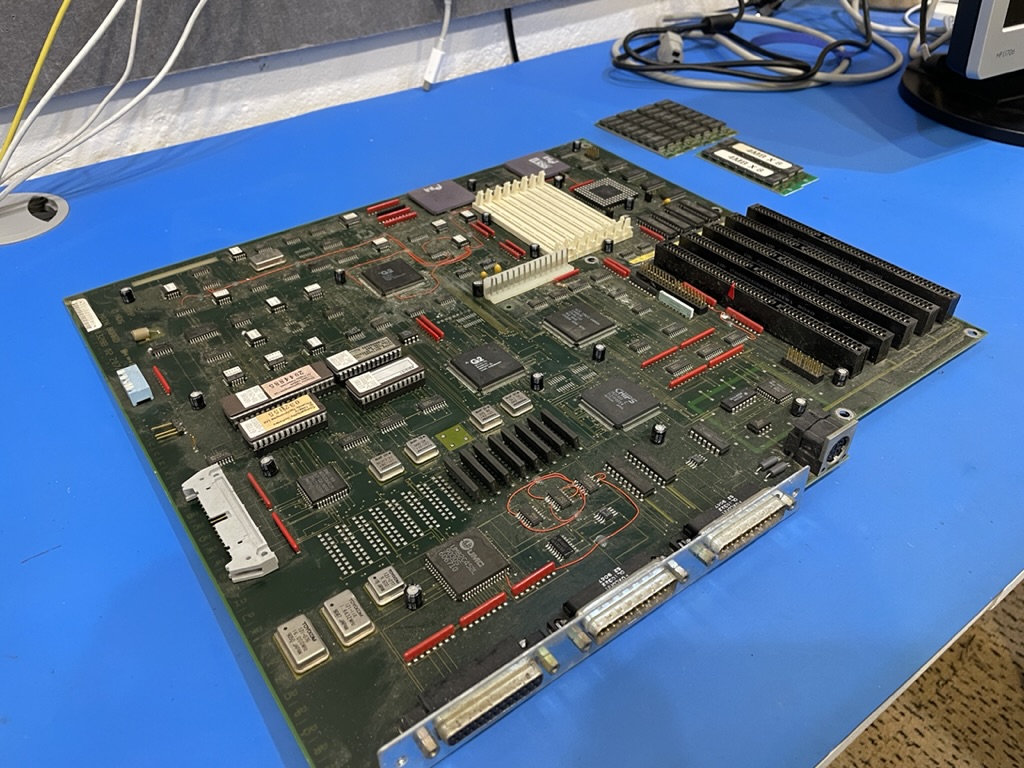
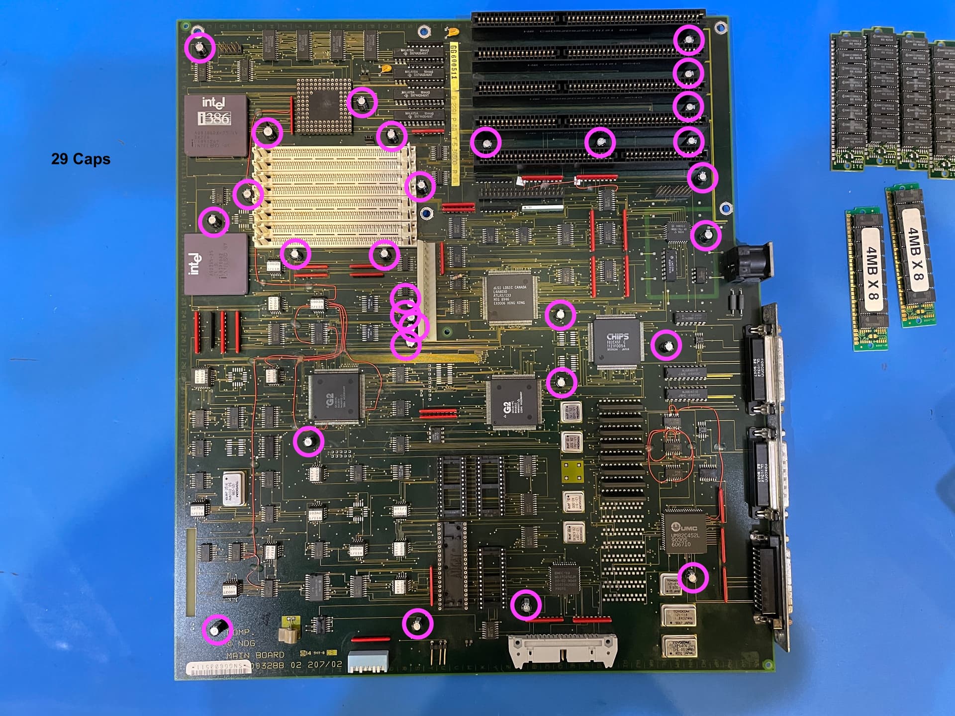
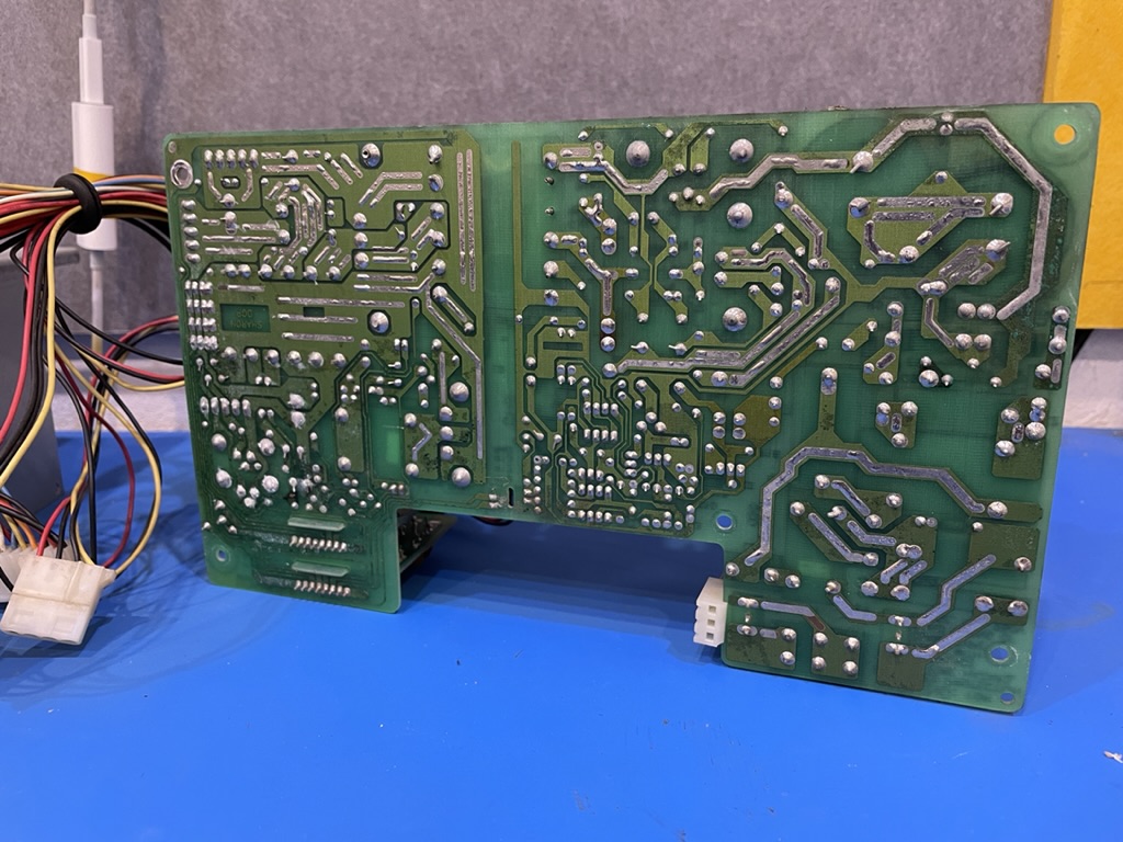
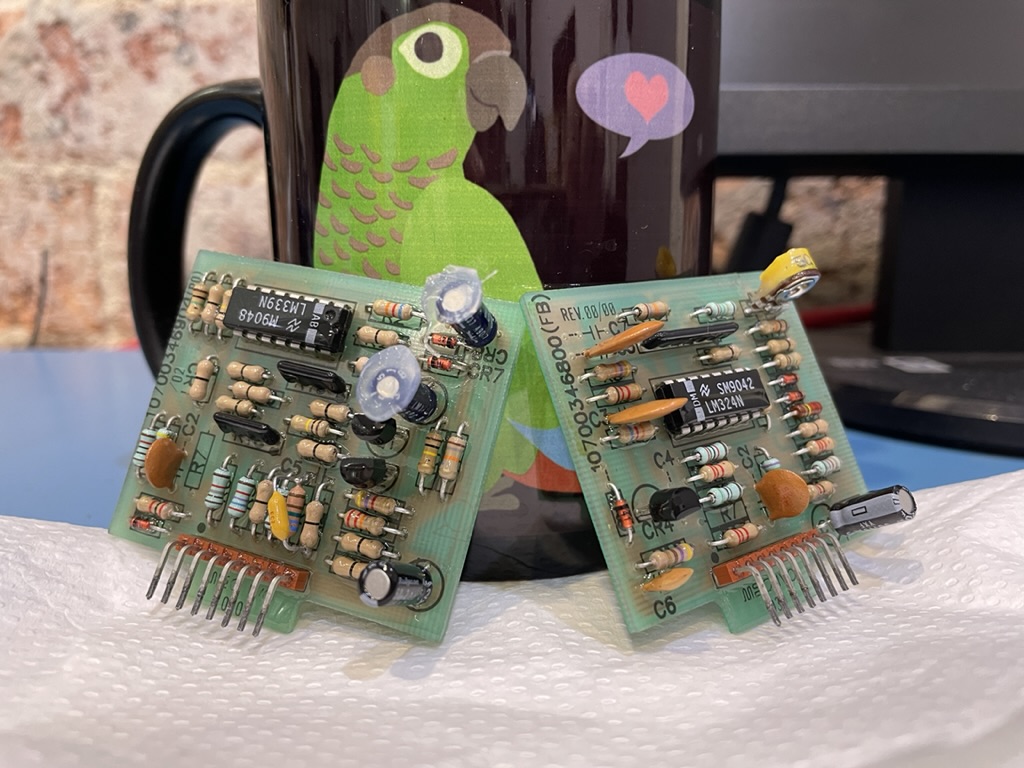
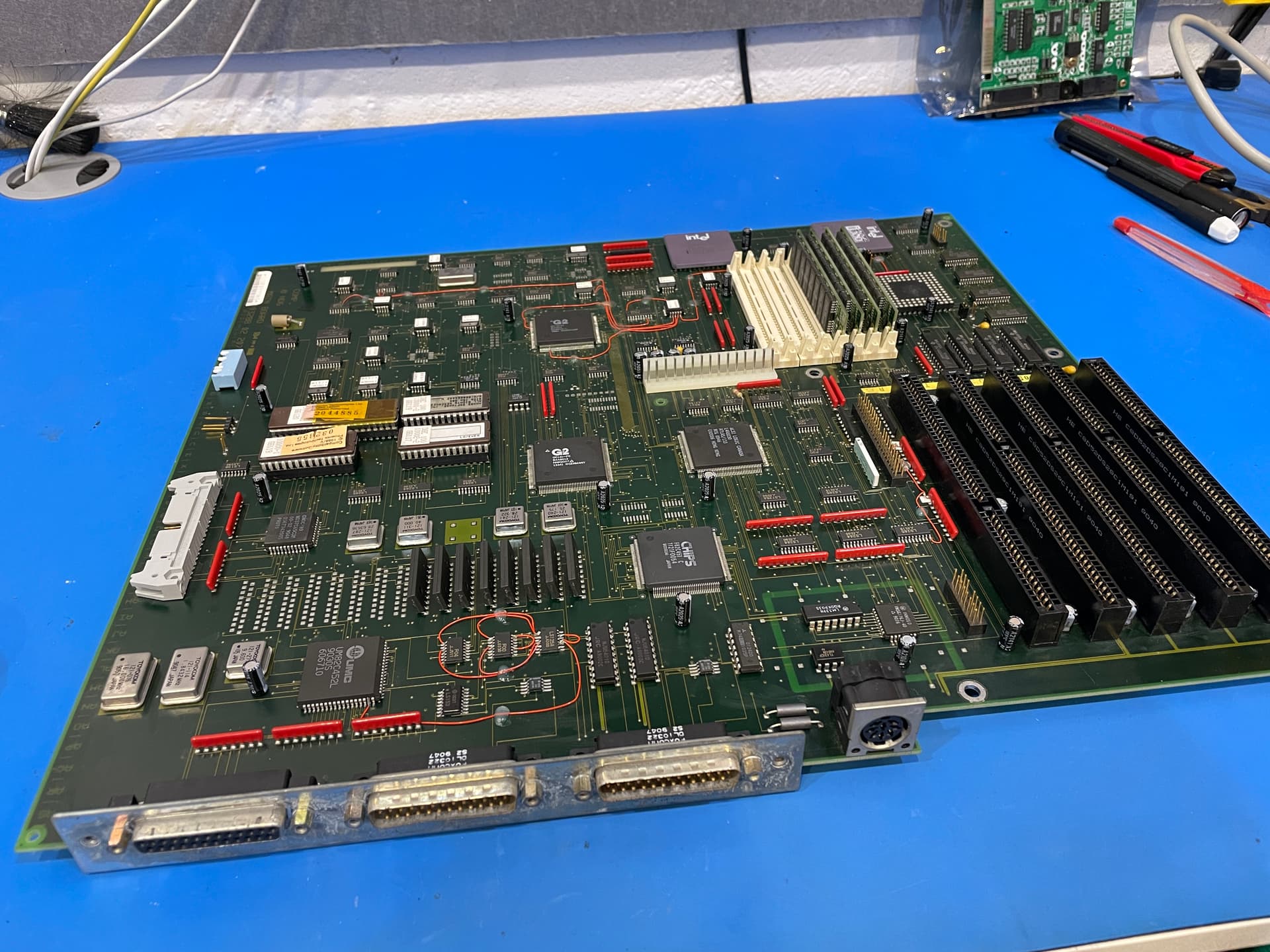
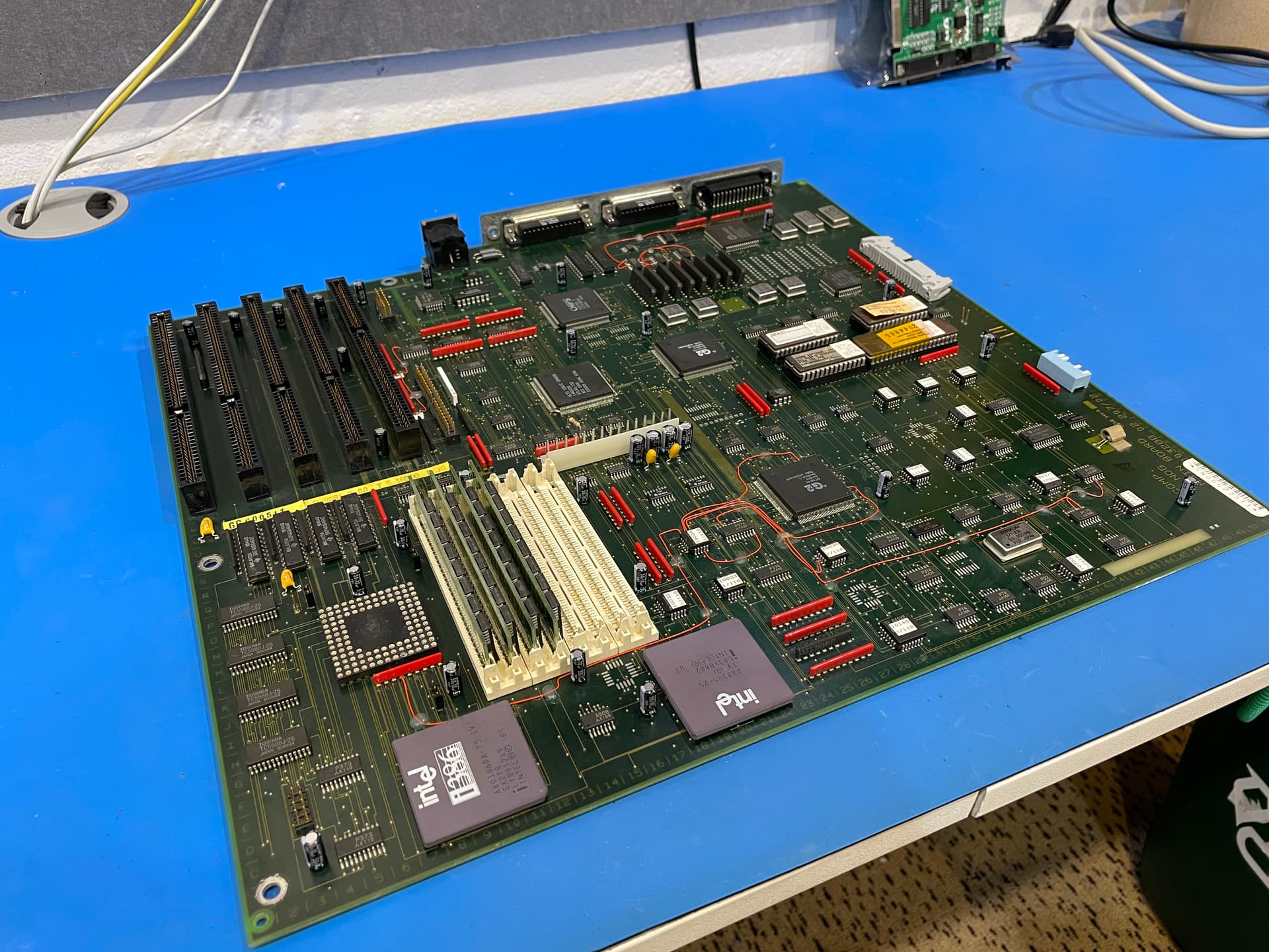
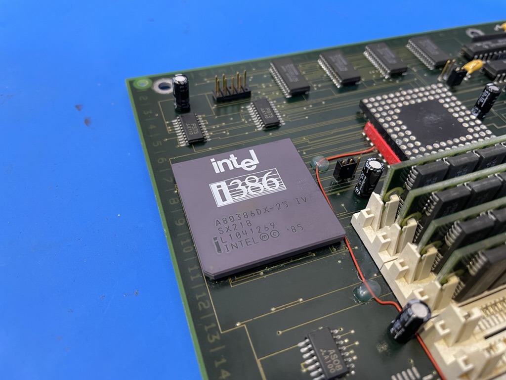
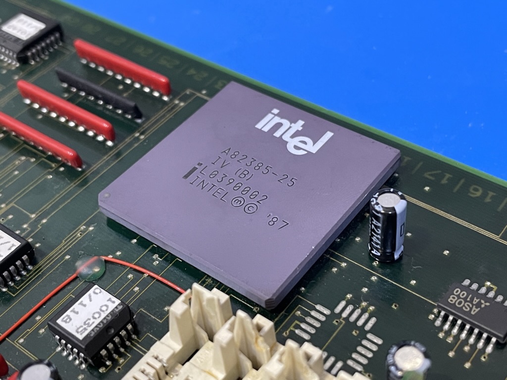
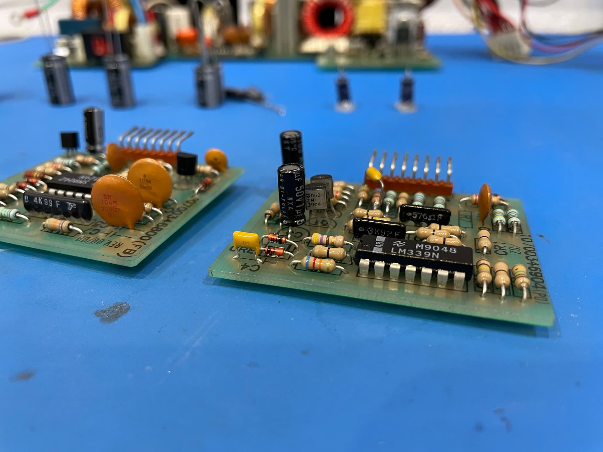
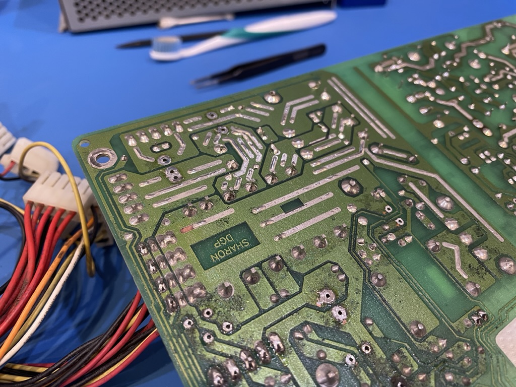
  • Recapping the main board (maybe).
  • Perform preventative maintenance on the Audio Drive ES688 with @ShaneMcRetro.

I hope the information above helps give an understanding of why we want low ESR, low impedance, high ripple current rating capacitors for the power supply circuit. Remember that this is my first dedicated power supply repair, I’m usually doing work on DC circuits. I’m hopeful we get a different result the next time it is connected to power. Until next update! :grinning:

The two jumbo resistors are the target in the power supply today. We’re going to remove them and clean inside those plastic protective sleeve tubing as they are trapping corrosion which will be bad long term.

Here’s the first one all cleaned up. Looks way better than before. I went with isopropyl to wash away some of the built-up corrosion while rotating the plastic sleeve. This one wasn’t too bad to begin with. Once the isopropyl had dried up, I applied some CRC 2-26 down the tube and used capillary action to soak most of it out the other end with a piece of paper towel.

Turns out they are 10k ohm resistors, I guess the colour code could have told me that. On to resistor number two - the green one.

Terrible, isn’t it? Let’s do the same as above but remove the sleeve entirely by slightly bending the leg and perform some light sanding on the really corroded areas.

That looks way better now. I am not sure what wattage these resistors are but they are definitely more than the 1/4 watt ones I usually encounter! :smile:

Here they are reinstalled, looking sharper than ever. One mission accomplished, let’s turn away from the power supply and put our sights squarely on the main board.

Look at those little fat capacitors, staring at me. Mocking me with their really large ground plane making desoldering slower than normal. They know what they are doing. We’ve already done a few here and there. Let’s do the rest, right now.

Alakazam! They are now Rubycon YXF series. Started at the CPU area because that’s where the worst looking capacitors were - bulging caps are never a good sign.

Working around the board, that’s now three quarters of the board recapped.

Just the ISA slots to do. Let’s double the height of those caps and get them filtering some ripple.

Aaaand done! The old capacitors seemed to not remove as easy as the caps that went in. They had a slight pattern in the legs that caused them to grip better. Quite annoying when trying to remove them.

But removed they are. And removed they shall remain. I found it best to reflow the old pads with new, leaded solder. Desolder with the Hakko 808 desolder gun and make sure they wiggle inside the via before removing. Some would require a second or third try with the reflow and desolder, but it worked.

I’ll post some photos of the key chips from the main board a little later on this evening. Overall - I’d say we are better off than we were 24 hours ago. :grinning:

In this post, we’ll have a look over the main microchips on the main board and what they do. First up we have the Intel 386 CPU. This is an A80386DX-25 IV that runs at 25MHz at 5V. It was introduced three years prior to this board being manufactured in April 1988.

Here we have the 386 cache controller, a A82385-25 IV (B). From what I’ve read these appear to provide the 386DX with L2 cache - great for a speed boost.

The UM82C452L looks to be one of the parts for controlling the parallel ports at the rear of the machine.

Need to copy that floppy? This chip will help you do that. The WD37C65CJM Floppy Disk Subsystem Controller.

This is the G2 GC131-PC Peripheral Controller. Part of a three chip “chip set” according to the datasheet for GCK131 from Headland Technology Inc.

This single chip effectively replaced two 8259, two 8237, 8254, an LS612, and other devices. The chip interfaces with an 8042 keyboard controller, real time clock, parallel ports, serial ports, speaker and the EEPROM used for power up configuration.

This is the G2 GC132-PC, CPU/Memory Controller. The second part of a three chip set.

This powerful chip decodes the processor address and control lines and generates the RAS, CAS and chip select signals required for memory management. Both statis and dynamic memories can be used. The GC132 Controller features both paged and interleaved memory access techniques that improve overall system throughput.

This is the LSI LOGIC CANADA L4A8030 ATLAS/133 and I can’t find anything on the internet about it. As we are missing a third 160-pin chip for the GSK131 to be complete, I’d hazard a guess this is the third chip. Photos online of the chip also show WGERMANY, while mine shows HONG KONG. It could be the fabled GC133 Bus Bridge Interface chip.

This is the Chips and Technologies F82C451 video chip. This is the onboard video card. One of these jammed onto a main board this small? How did they do it!

These standing upright chips look to be my video RAM for the F82C451.

Well, that ends the tour for now. There’s not much left for me to do except wait for the power supply capacitors to arrive. They’ve reached the continent, just need them to make their way to the mailbox.

I’ve asked some people in the retro scene to see if they can provide some loan parts that might help when… if… the machine does power on first time. It’s reassuring to know we’ll have a known working floppy drive with floppy disks. It’s all coming together now! :partying_face:

They’re here. Let’s begin. Look at that 6800uF, voltage upgrade and only slightly taller. 2200uF, I wish I could have got a taller one but there just wasn’t one available in that dimension from Rubycon. The 1000uF went superwide with the extra 5mm to 7.5mm lead (leg) width. It also gained 4mm of width, which was OK as this was as dual 12mm/16mm width silkscreen with both leg sizes available.

Nothing too interesting happening with the 330uF and 220uF capacitors.

47uF, 1uF bipolar/non-polar were all pretty standard swaps. The 0.47uF bipolar/non-polar got switched to a multi layer ceramic capacitor (MLCC). Going by the silk screen it looks like they intended to use ceramic but ended up putting on an electrolytic bipolar/non-polar at the time.

Speaking of those two, let’s put them on the board immediately. They go on one of the sub-boards, just need to make sure I add some hot glue to the top of the 1uF non-polar capacitor otherwise it will short the back of the board in front of it - that would be bad. The MLCC is visible at the front.

Now for some shots of the newly installed Rubycons:

Absolutely stunning. But we had a little issue with the hot glue holding the really big (non-replaced) capacitors on the high voltage side of things.

The isopropyl alcohol and CRC 2-26 have caused it to detach.

I am terrible with the hot glue gun.

At least they won’t take off into orbit now when we flip the switch.

With all the capacitors in, the sub-boards/daughter boards can be soldered back in.

See that short I was worried about? The hot glue wasn’t holding the boards together, it was stopping the capacitors shorting out on the other board.

Looking good enough, the glue dried before I could jam the board up against it. It’ll do the job it needs to do.

That’s it, we’re done.

Well, I guess we need to reconnect the ground, +5V and multi-colour cable to the sockets.

That’s right, it was so long ago I forgot about this mess. Time to get the AC area hooked back in and probably earth too.

That looks about how I remember it being.

I don’t want this to be exposed when I turn it on. Although I triple checked the components, I just don’t trust old power supplies.

I feel safer already. But how should we test? I don’t want to risk the main board just yet.

Maybe, we’ll just try something like this. I am a little concerned that there is no load. I should probably add some load to the rails. Then again, I could also just flip the switch.

+5.00V with no load. Let me just zoom in on that.

+5.02V, even better. But wait, the fan doesn’t start up? It tries to tick over but doesn’t engage. The fan runs off the +12V rail. That’s not a good thing, right? Let’s check the voltages, remembering that +12V was perfect before work began…

+6.60V is as high as the +12V rail would read in the 20 seconds it was powered up.

And the lowest we saw was open loop (O.L) - there was a whole range of voltages in between.

Troubleshooting time. What can we test without taking this thing apart again, knowing it is a pain to disassemble. Resistance. Let’s check the ohms. 242 ohm between +12V and GND. All other rails (including the negative rails) were showing ≥0.5k ohm resistance; many resistances more… is this an issue? Have we shorted ground to 12V somehow? Is a newly installed capacitor faulty?

I stared at old photos of the underside of the board, tracing where +12V and ground may have collided for about an hour and then decided to call it a night. The long walk home gave me time to run through some ideas. What if 240/250 ohm is normal for this board? What if we need load on the rails for them to engage? There is a +12V headed to the main board. We don’t have the main board attached. I did some digging, this is what I found.

Source 1 - The symptoms are close enough, 250 ohm resistance, fan powers on briefly then powers off.

I don’t think that you need to worry as long as the resistance you measure doesn’t show a real short circuit. I quickly measured the impedance shown between 0 and 12V on two good ATX power supply that I have lying around here - I also got 250 Ohms on one and 120 Ohms on the other.

Source 2 - Clicking noise, trying to switch on. Sounds familiar.

The PSU will only switch on with a certain load attached to it. Usually it is sufficient to hook up a hard drive or an old floppy drive in order to get a computer PSU to start properly. Without load it will either not start, or try to switch on but make a clicking noise. Without load it is also not possible to measure any output voltages.

Source 3 - This is the light bulb moment.

PC power supplies use a technique called switching to generate their DC voltages. Due to the manner in which these sorts of power supplies function, they need to have a load, meaning something that draws power from the supply, in order to function properly. A power supply that is turned on with no load attached will either fail to function or will function improperly. Better-quality supplies will detect a no-load situation and shut down, but cheap ones can be damaged. This is why you should not “test” a power supply by just plugging it in with nothing attached to it.

Whoops. Already did that, unless you count the multimeter as load…

In the early days of the PC, power supplies often had considerable load requirements, both for the +5 and +12 voltages. The +5 voltage requirement was easily satisfied by connecting the power supply to the motherboard, but the only devices that draw +12 V consistently are hard disk drives.

We are certainly not connected to the main board. What if it is as simple as that?

Thus, people who tried to troubleshoot power supplies without connecting a hard disk drive could be tricked into thinking the supply was bad. Also, systems with no hard disk drives would have a problem starting up unless equipped with a “dummy load”.

Well then, consider me tricked! This machine would have shipped with a hard drive. That said, it might be new enough to not require the +12V dummy load. I need to plug that power supply into the main board tomorrow morning… for now I will sleep and dream of Microsoft Solitaire. :black_joker::black_joker::black_joker:

2 Likes