Incredible work. Really happy to see this.
Hoping you are able to power it up soon!
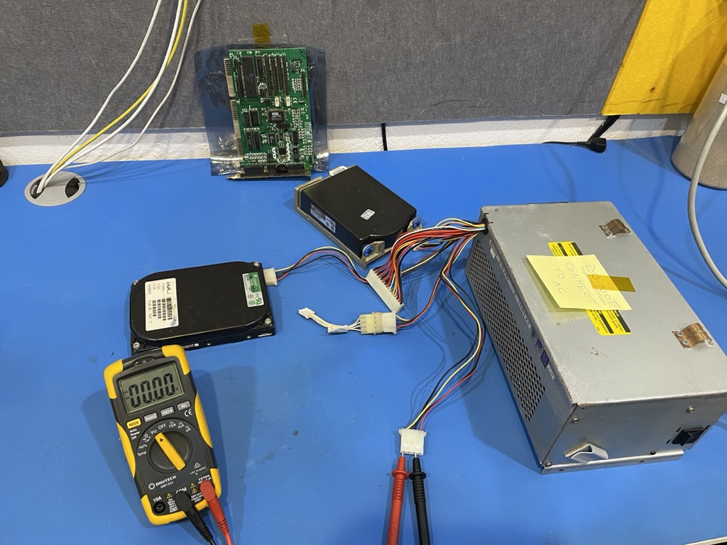
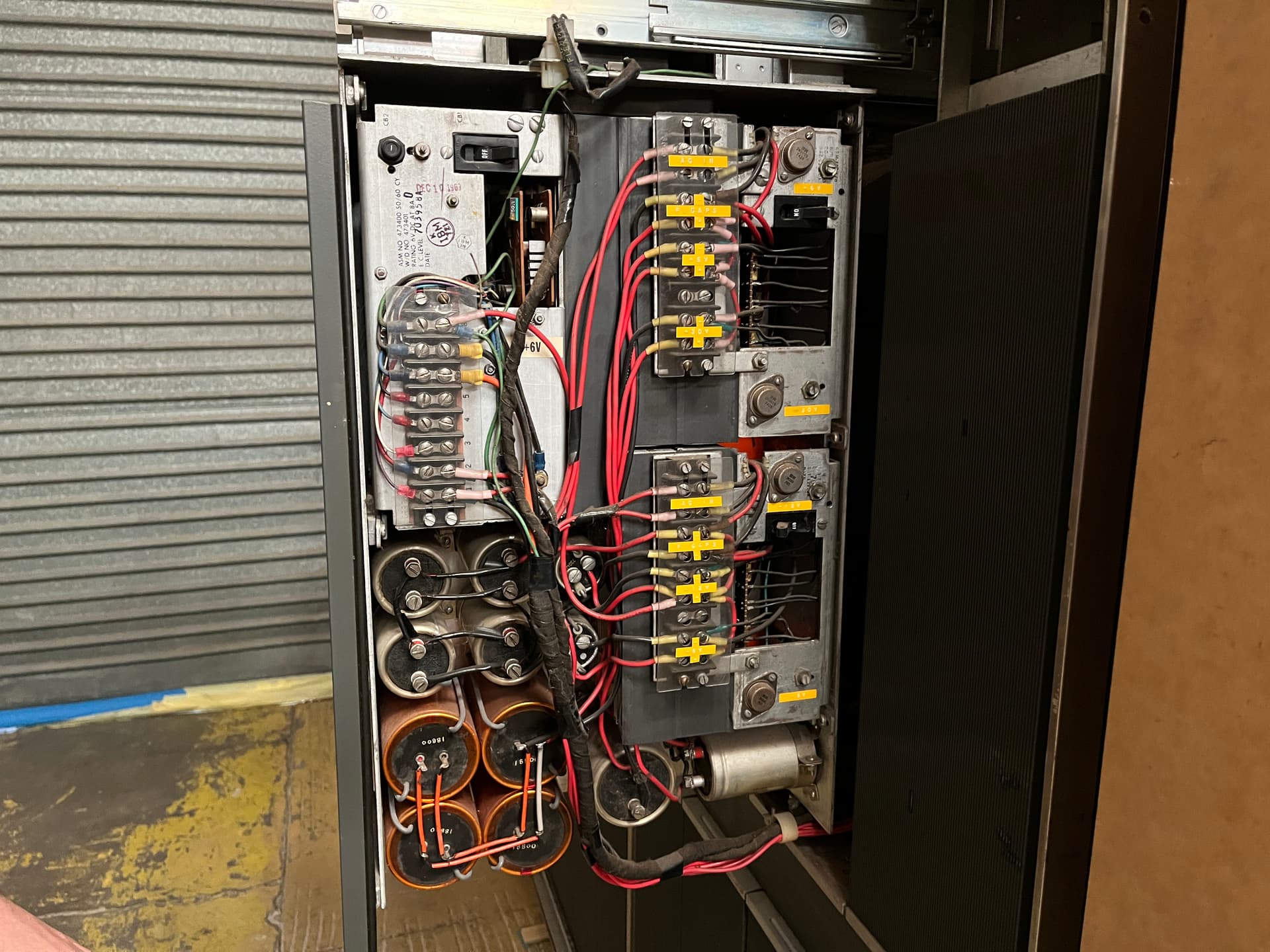
Two hard drives should be enough to draw some current. Let’s see what happens to the +12V rail now. We set the multimeter to manually be on V, not autodetect as that could mess with the numbers as the meter can’t work out the range quick enough before the voltage changes.
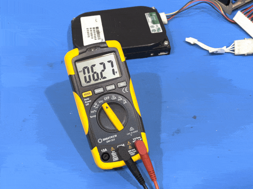
Uh oh, that’s not right. It’s jumping between 6.2V and 2.9V on the +12V rail. What about the +5V rail, that looked alright in the previous post.
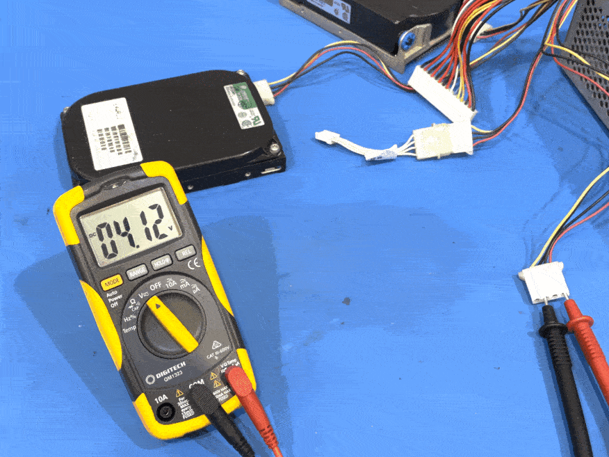
Hmmm, alternating between 4.1V and 1.8V. The +5V rail is not working either. So why did it work yesterday? Was it the lack of a load on the rails perhaps? Does the +12V rail being connected cause a short somewhere? Is there an actually an issue with ground being short? Someone much wiser than me advised that this is what a crowbar circuit looks like when it is activated.
A crowbar circuit is an electrical circuit used for preventing an overvoltage or surge condition of a power supply unit from damaging the circuits attached to the power supply. It operates by putting a short circuit or low resistance path across the voltage output (Vo), like dropping a crowbar across the output terminals of the power supply.
I really do not want to pull that power supply apart again, unless we have some sort of guarantee of success with the main board powering on. As we’re running out of days and I’m running out of allocated money for this project, I’m going to try integrating a modern (<20 years old) power supply that I found when cleaning up the garage.
All I need is an adapter from ATX to AT to arrive from overseas. This was ordered as a potential backup plan mid-October - it could turn up any day now. Cross your fingers for me! ![]()
1 Like
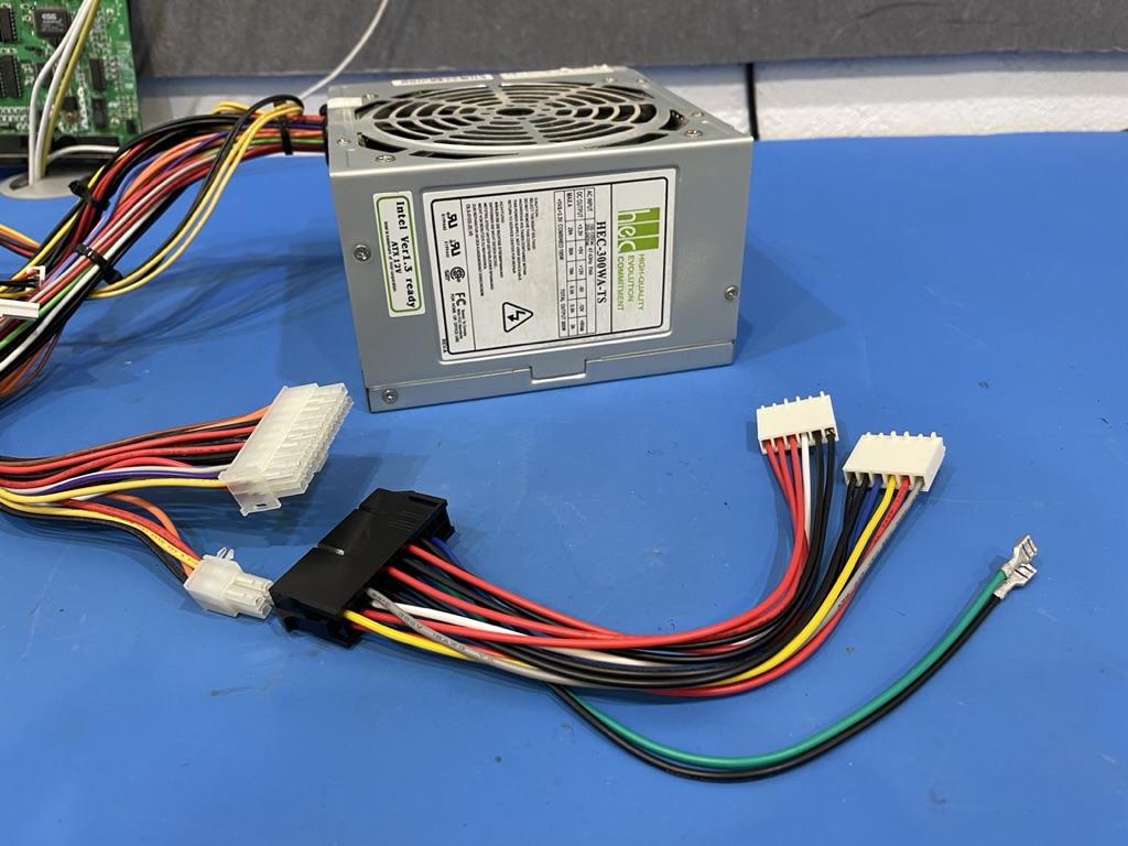
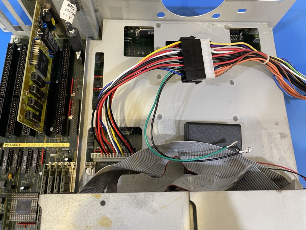
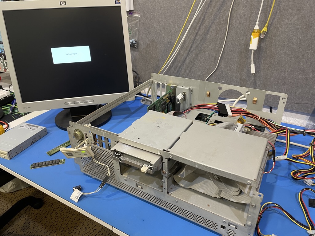
It arrived, unbelievable. ETA was next Tuesday but for whatever reason it actually turned up early. You can see the ATX power supply in this photo too with the voltages it provides. Note the inclusion of the -5V and -12V rails.
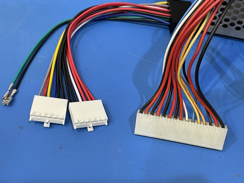
First thing is to get the standard AT power supply connector to rewire to match this bastardised plug Data General thought would be fun to use.
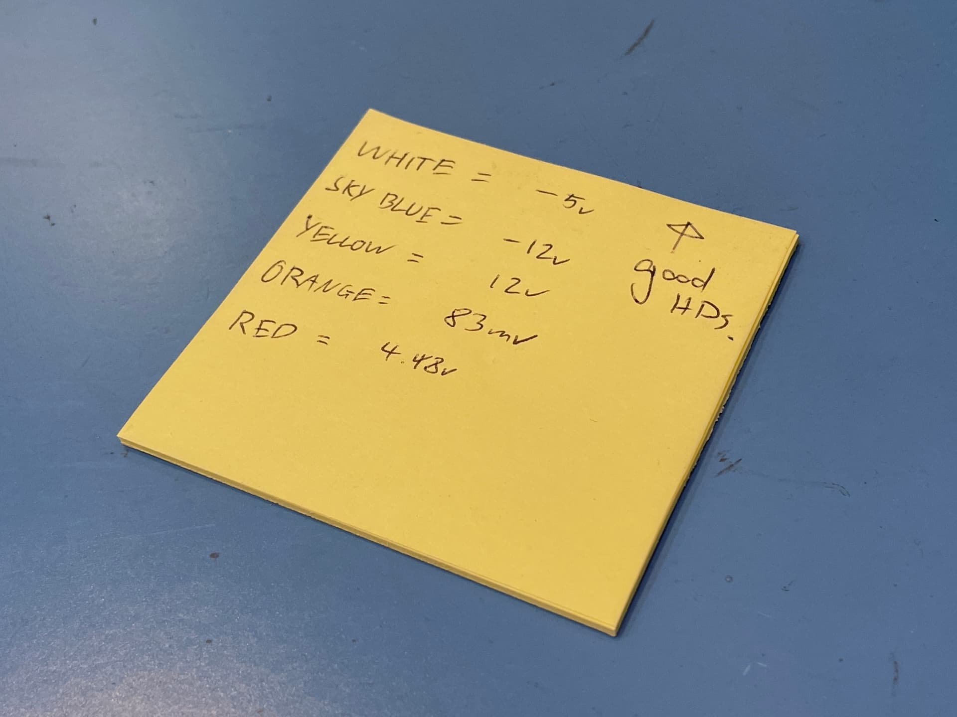
We just need to match the colours as the Dasher 386 power supply is pretty standard in that respect. The colours mean what they mean. +5V red, +12V yellow, -5V “sky blue”, -12V white, GND is black, etc, etc. The good news is the pins look to be the same in each connector…
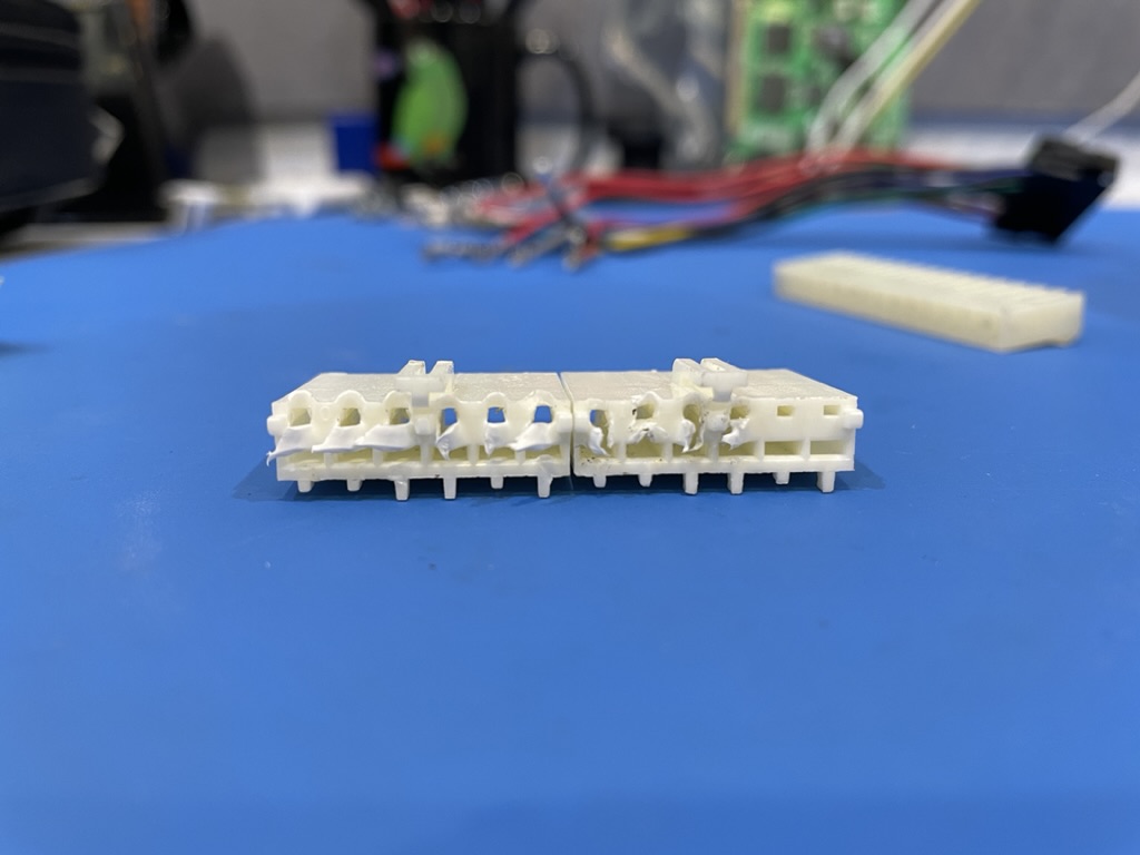
And the bad news is that the AT connectors had to be irreversibly destroyed to remove the pins. There’s no recovering from that.
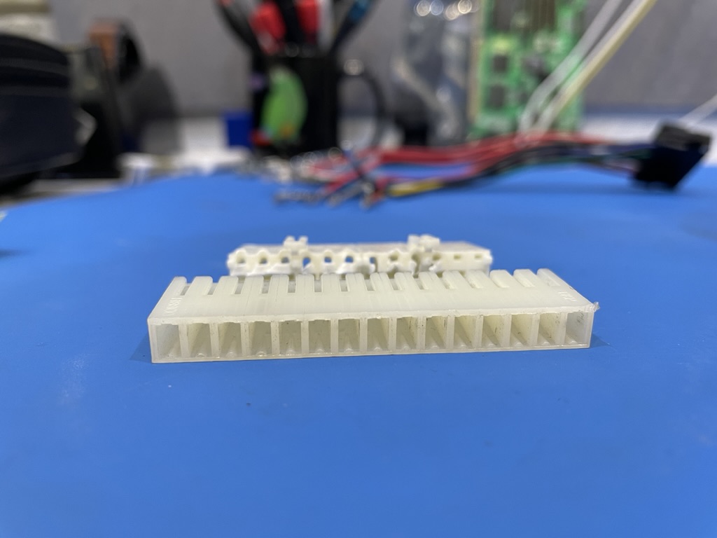
The Dasher PSU socket was much nicer to remove cables from and resulted in no damage and took 1/10th the time to remove the cables. They just don’t make them like they used to!
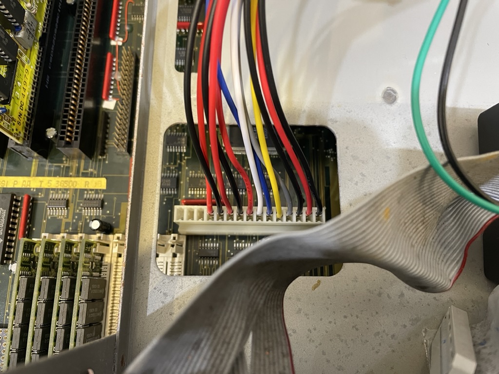
The missing pins were found to be common with each other. The missing +5V and GND were already shared with others so that’s no issue. Grey is our “Power Good” signal (instead of orange on the original PSU).
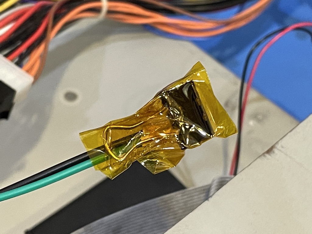
Zooming out we see that we also have a green and black wire. We need to tape these together to power on the machine. Ordinarily they would be on a switch, which I am not digging out of the power supply just to test. We’ll try something a little unconventional.
A bulldog clip which is also know as:
A binder clip, less commonly known as a paper clamp or foldover clip or bobby clip or clasp, is a simple device for binding sheets of paper together. It leaves the paper intact and can be removed quickly and easily, unlike the staple.
I couldn’t use staples so a bulldog clip wrapped with Kapton tape to prevent any damage to surrounding people or components.
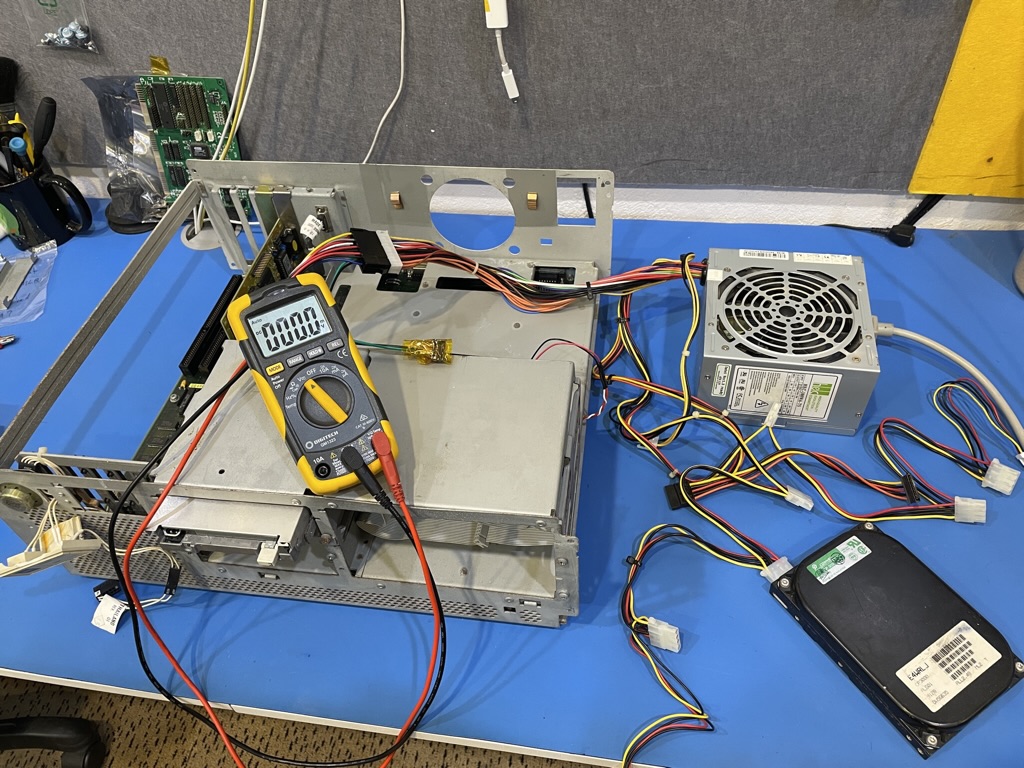
Initial power on showed all power rails in good shape.
However, our symptoms were the same as before starting the project. We tried changing jumpers around, RAM configurations, reseating ROMs in sockets but it all came down to no video and really, as far as I could tell - no POST with either the onboard video chip, or three other video cards we had on hand for testing, in any one of the ISA slots.
So where does this leave us and what are the next steps?
Well, from what we have seen it looks like we have an issue with the mainboard and now the original power supply. Unfortunately, I don’t have the equipment or skill to diagnose and repair either of these at this point. I’ve over budget and out of time, I do wish that RetroChallenge was two months long. One month doesn’t seem like enough if you hit any snags - which I certainly have.
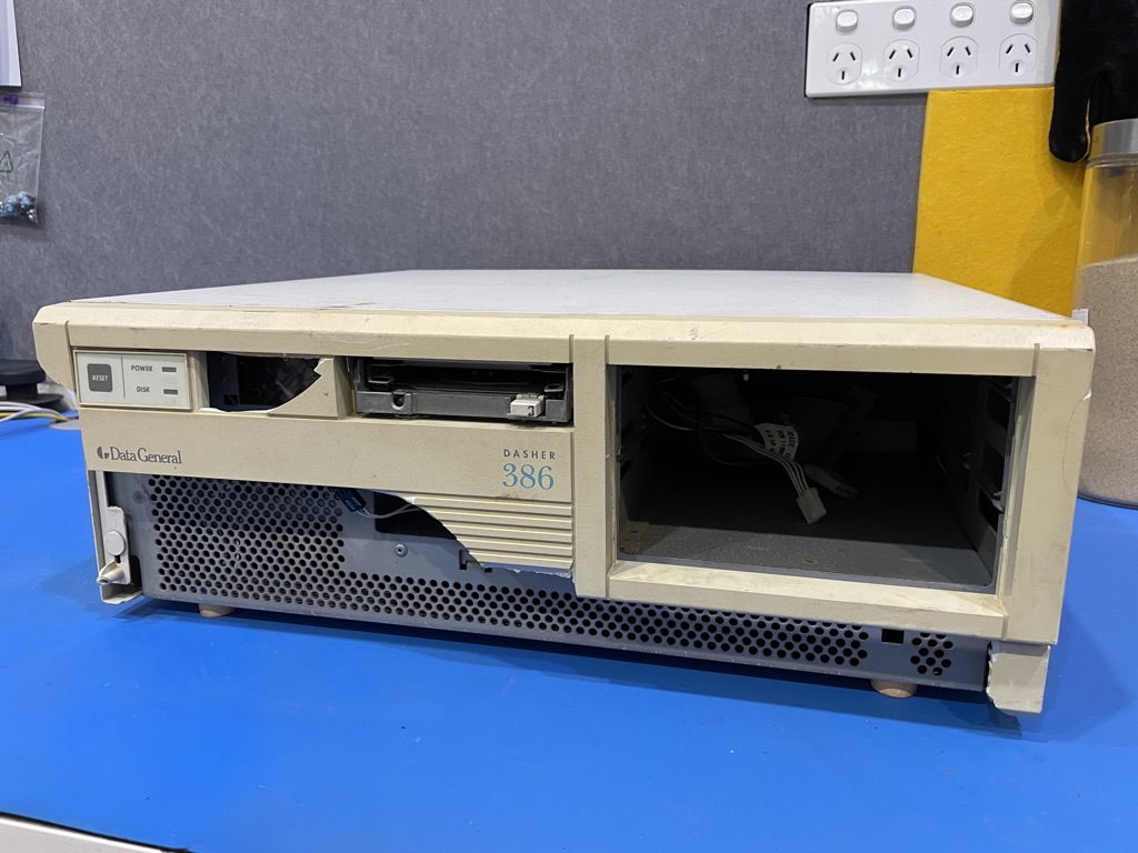
I’ve reverted the power supply connector back and put the machine as much into it’s original configuration as when I found it - with a warning on the power supply AC inlet to not connect to power.

This has certainly been a a learning experience. I now know a lot more about which capacitors are best to replace in power supply circuits. I also know a fair chunk more about how a 386 should work. That’s not to say I’m a little disappointed that it didn’t work out, but it’s important to know when to stop. We’re now at that point. Next up is a little more information on the history of Data General from this fantastic archive.
Their FOCUS_1989-06-Jun edition reveals this tidbit:
DG adds Dasher/386-25 to Unix family
Westboro-Data General has announced the Dasher/386-25 personal computer, an addition to its industry-standard Dasher/386 Unix family that incorporate a 25 MHz Intel 80386 microprocessor.
And it goes on to say…
The Dasher 386-25 is faster and more powerful than the entry-level Dasher/386, providing minicomputer performance and functionality for the price of a personal computer.
Which means that this machine may have been a more advanced version of the Dasher/386 given the model is a DASHER 386-25K. I’ll mirror the ‘FOCUS’ magazine collection for some light reading in the future on my web server at http://retrojunkie.net/files/. Any one who wants to is welcome to add any information they can about the Data General Dasher 386 into this thread.
Thank you to everyone who has been reading along, I hope you enjoyed and learnt something along the way, I know I did! ![]()
3 Likes
Found some more information on the “Dasher/386-25k” in a 1990 edition of PC Magazine. ![]()
The Dasher/386-25k is a brand-new design with a list price of $5,690.
… looking for a design in a relatively small package. Relative to what? A mini-bus? ![]()

Look at that performance though, the Data General takes on all the big names and sends that orange bar soaring.
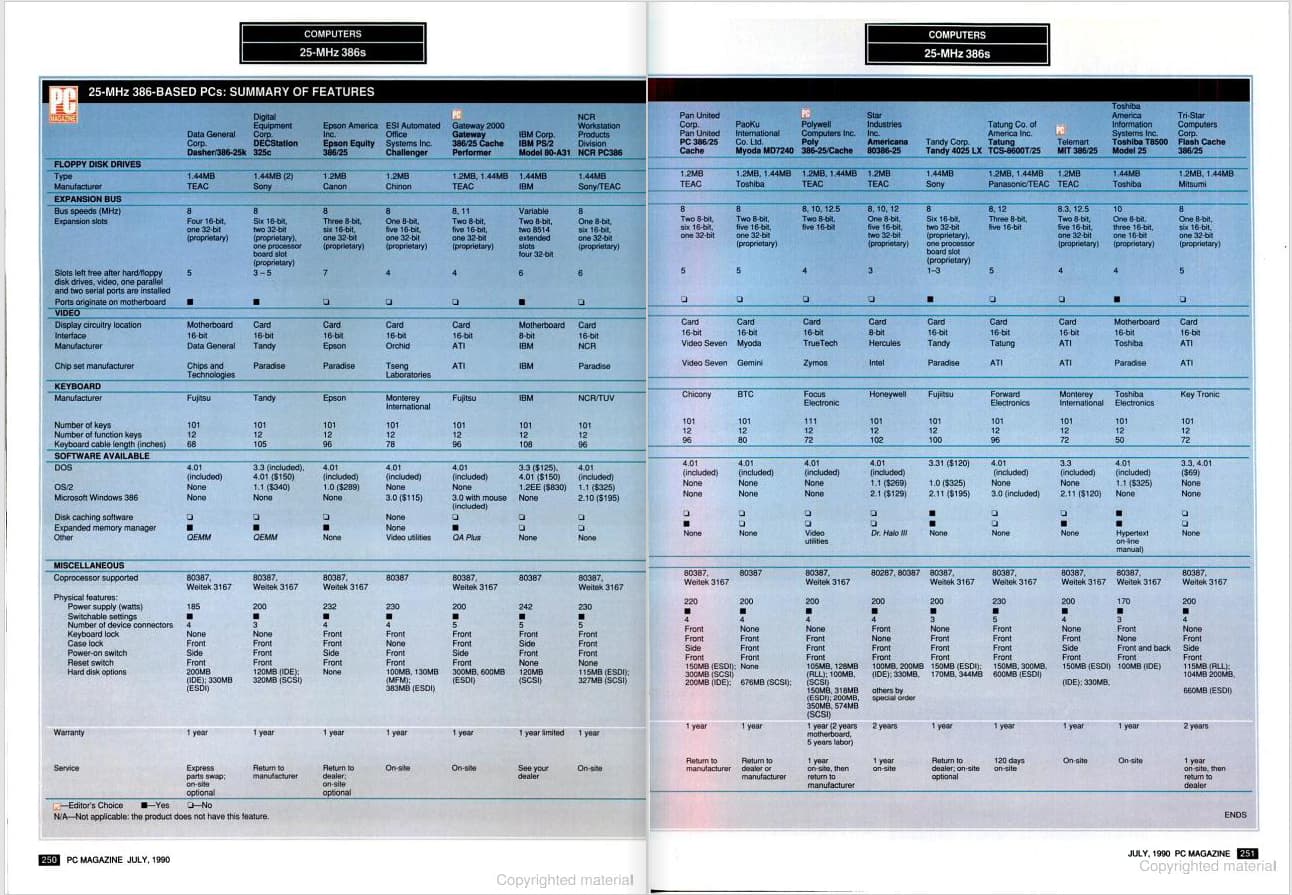
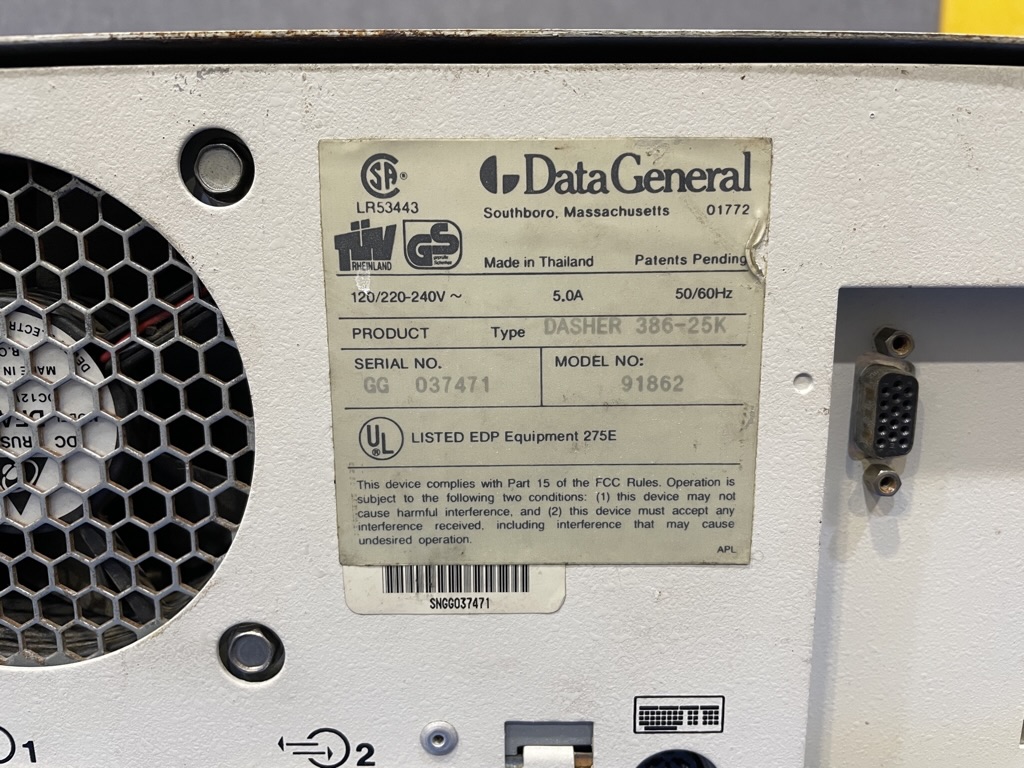
There’s some interesting specs. We have 200MB IDE and 330MB ESDI (Maxtor) hard drive, 185-watt power supply - now we know. Video chip was from Chips and Technologies and manufactured by Data General. The keyboard was a Fujitsu.
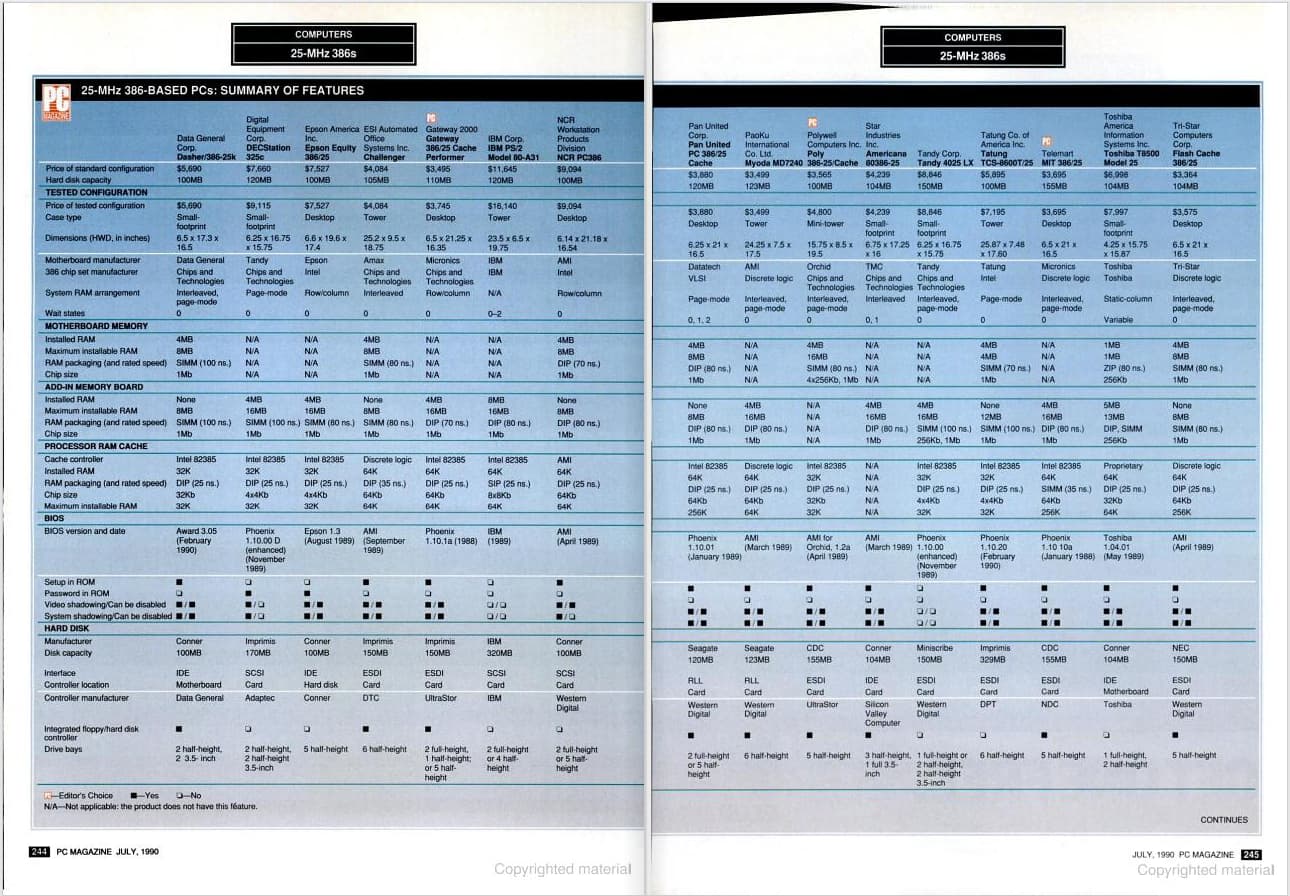
Default included hard disk was a Conner 100MB IDE. The case type was “small-footprint”. Maximum onboard RAM was 8MB (8x1MB SIMMs, 100ns). Not forgetting there was that proprietary RAM card that could double the RAM with an additional 8MB, with the same configuration as the mainboard by the looks. Quite interesting.
2 Likes
Those dark marks on the traces are likely corrosion of the underlying traces below the solder mask. Eventually you may have to bridge these with a jumper wire or sometimes scraping off the mask you can add a bit of solder to rebuild the track, although this normally requires scraping it back to bare copper first.
1 Like
Rubycon, great choice and my favorite brand of cap.
1 Like
I’ve also fallen for that trap in the past. Now I know you normally need an adequate load on the +5V rail so that the switching pulses are wide enough to generate voltage on the +12V rail and any others too.
It’s possible that before you replaced the caps that your +5V rail was leaking enough that it was creating ‘THE’ load and that’s why you saw +12V.
2 Likes
Ahhh right, that makes a lot of sense if the trace under the solder mask is broken then it’s big trouble for the board unless it is repaired. I honestly didn’t realise that corrosion could get under the solder mask! Clock that up to another thing learnt.
When I have some more free time I may go poking around all the various traces now that I can use a known working power supply to test. Those traces are tiny though, I wish I had one of those desk lamp magnifiers to make the work a bit easier.
Interesting theory, it would explain where some of the +5V rail was going. It’s tricky to leave it be because it’s so much fun to play with but such a time vampire! ![]()
![]()
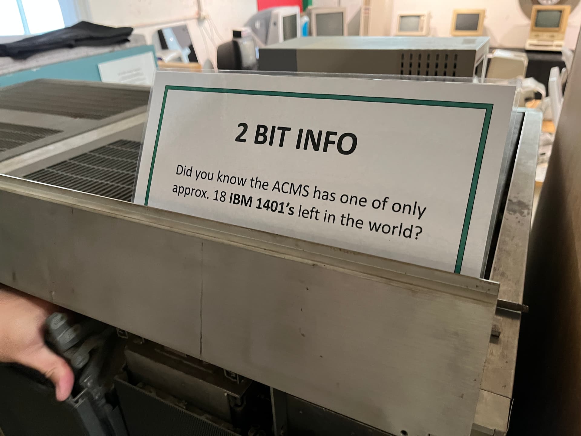
@SuperNick - We are pleased to advise you are the grand prize winner of the October 2022 RetroChallenge! Please get in touch to collect your prize from the ACMS workshop! CONGRATULATIONS!
Prize - 10.1 " Digital Microscope worth approx $450!
2 Likes
Wow! Thanks for the prize, I was not expecting that! I didn’t even know there were prizes! Come to think of it, I might be able to use that for board inspection to help with fixing the traces on the mainboard that might be causing some issues. Regardless, I’ve sent you a PM! ![]()
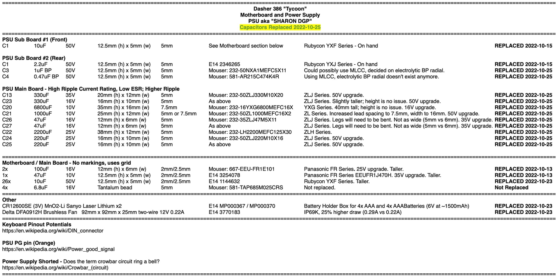
Here’s the latest revision of the capacitor values and what I replaced them with for reference. I’m out of the area on business for a while now so I’ve sent over all the video footage I have to @ShaneMcRetro to put together and upload to his YouTube channel. It’s mostly information that already exists on this page but it would be good to have it saved somewhere else too. ![]()
3 Likes

Don’t ask me how I was able to voice it over by rambling for over an hour, The video should be high enough quality at 4K for all the photos to show up nice, clean and any text should be readable.
@Pendleton115 I threw in a bit about your iMac G4 rebuild because let’s be honest, halloween is the best time of year! ![]()
@SuperNick I look forward to trying out the microscope! ![]()
I hope someone enjoys or finds the photos useful. My rambling isn’t that useful but the photos should be of great help for any future visitors.
All the best and congratulations to all who won the RetroChallenge 2022/10! ![]()
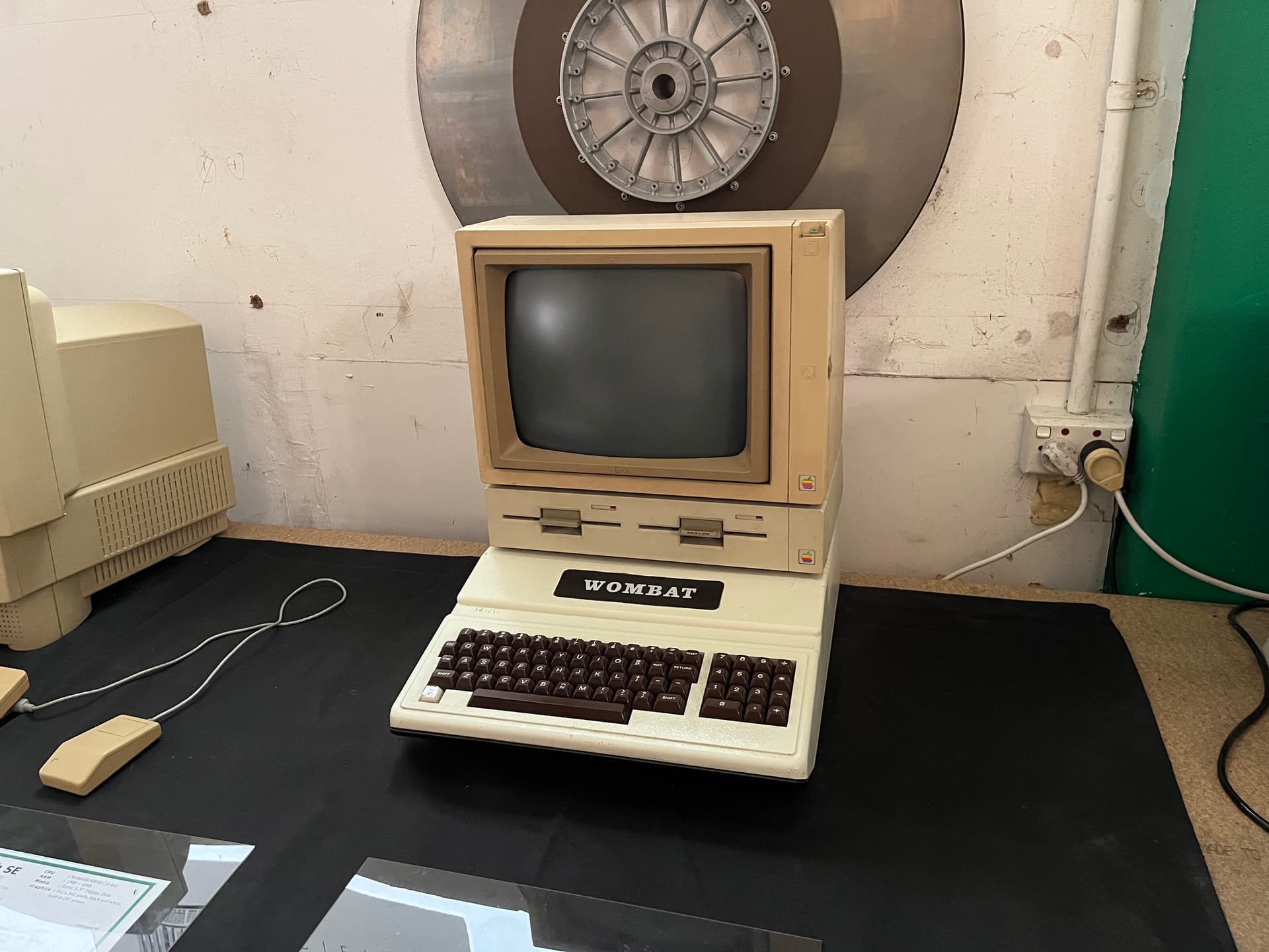
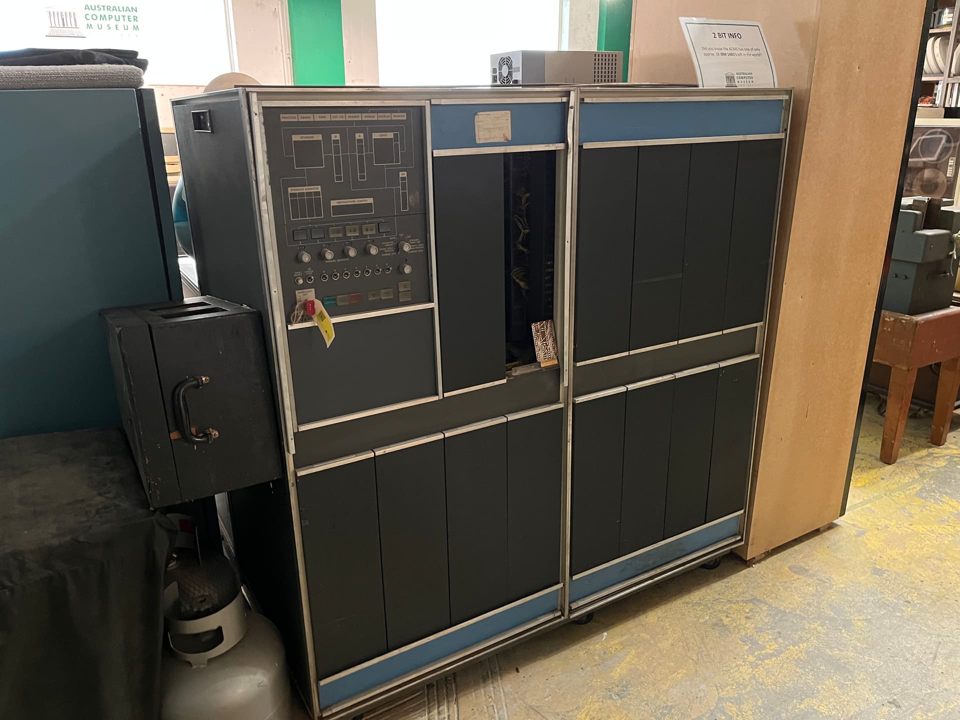
I’m back from work trip and last week (or so) I met with Adrian at the ACMS in Croydon on the 18th March. I picked up the microscope prize and took a grand tour. Thought I might share a few photos for preservation of how the ACMS is evolving.
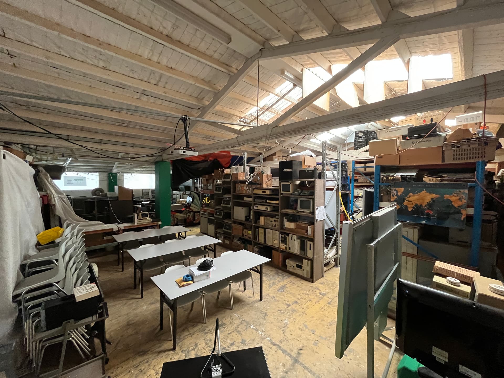

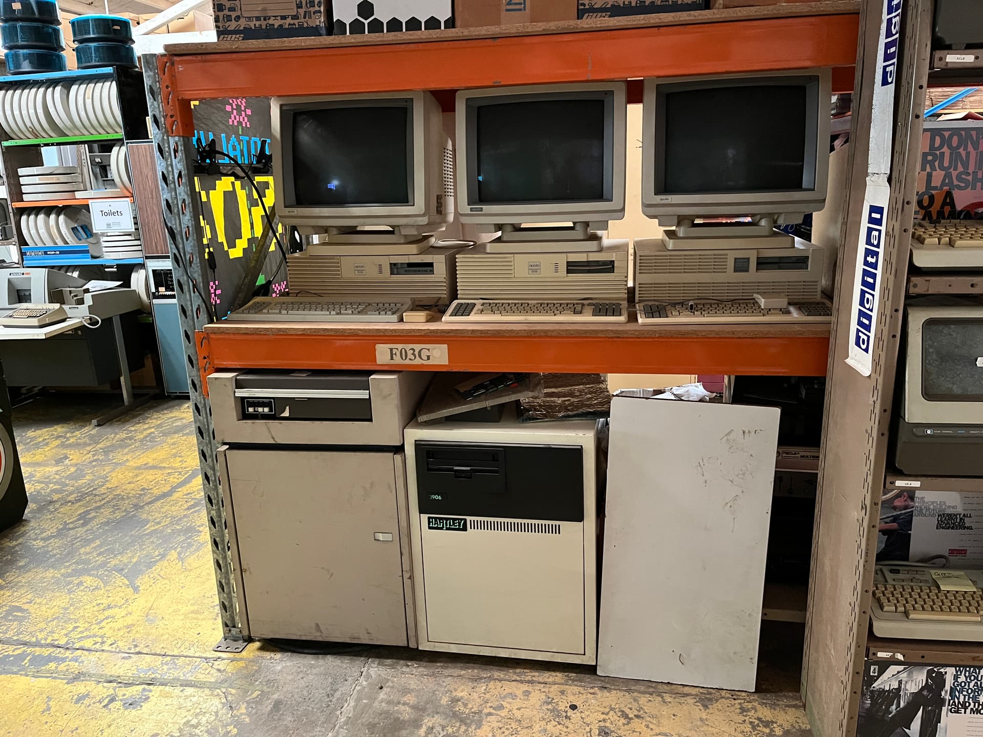
I’m not allowed to show behind the scenes, but there’s a lot going on back there. Incredible work really. Here’s some more from the main floor.
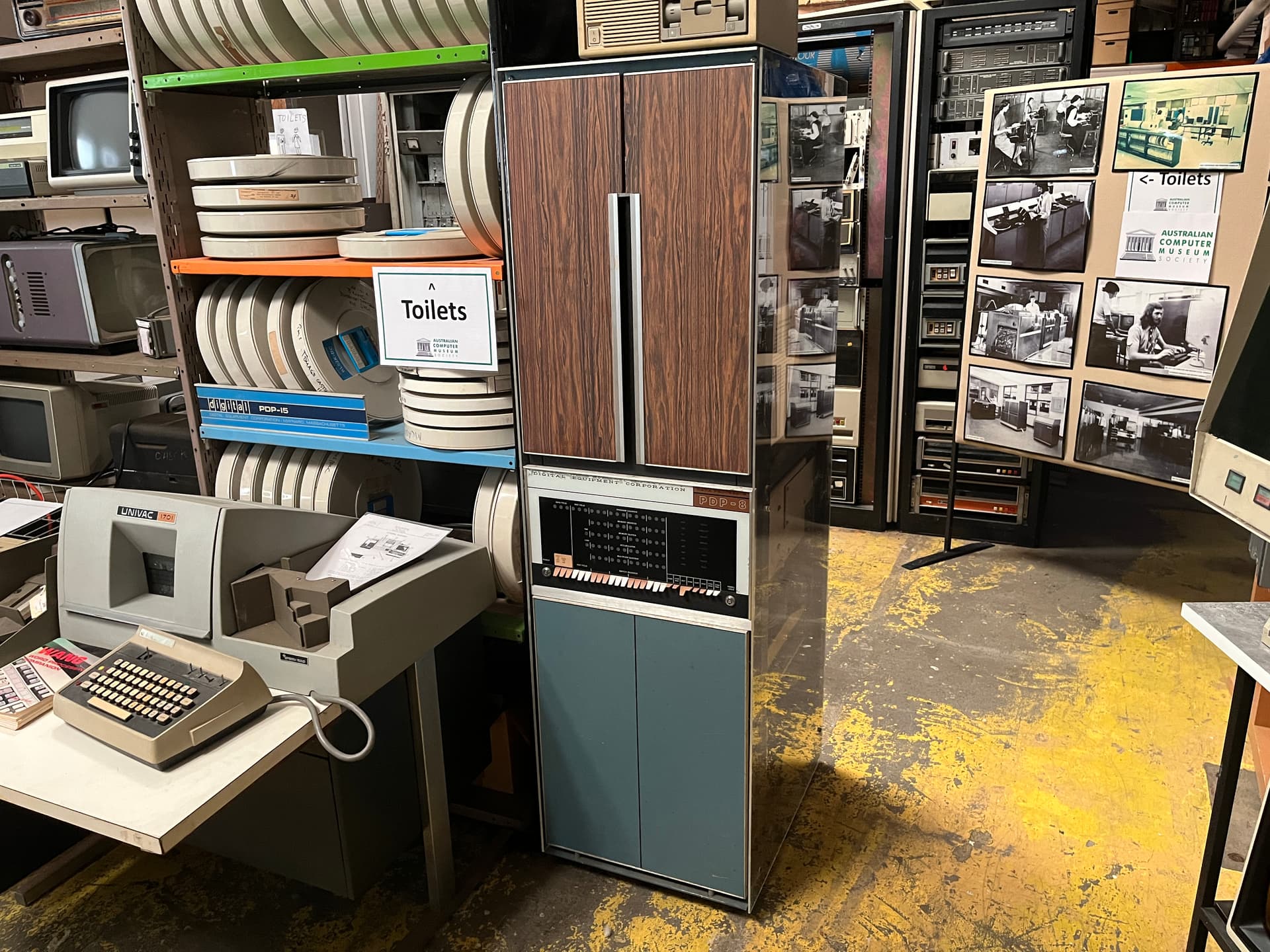
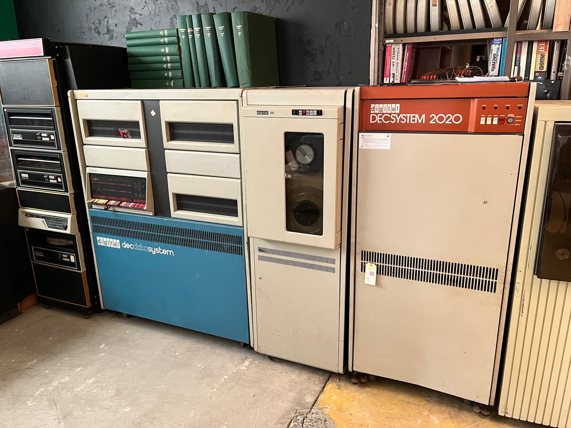
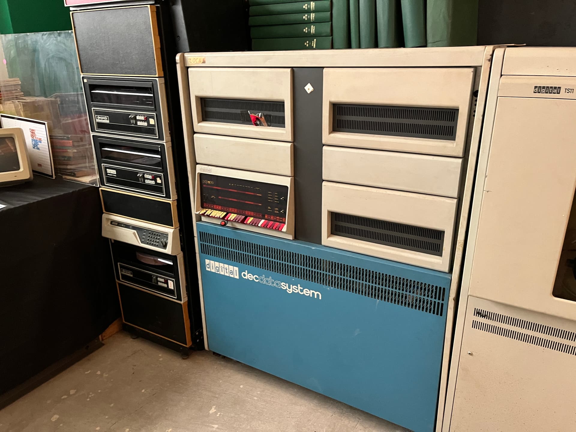
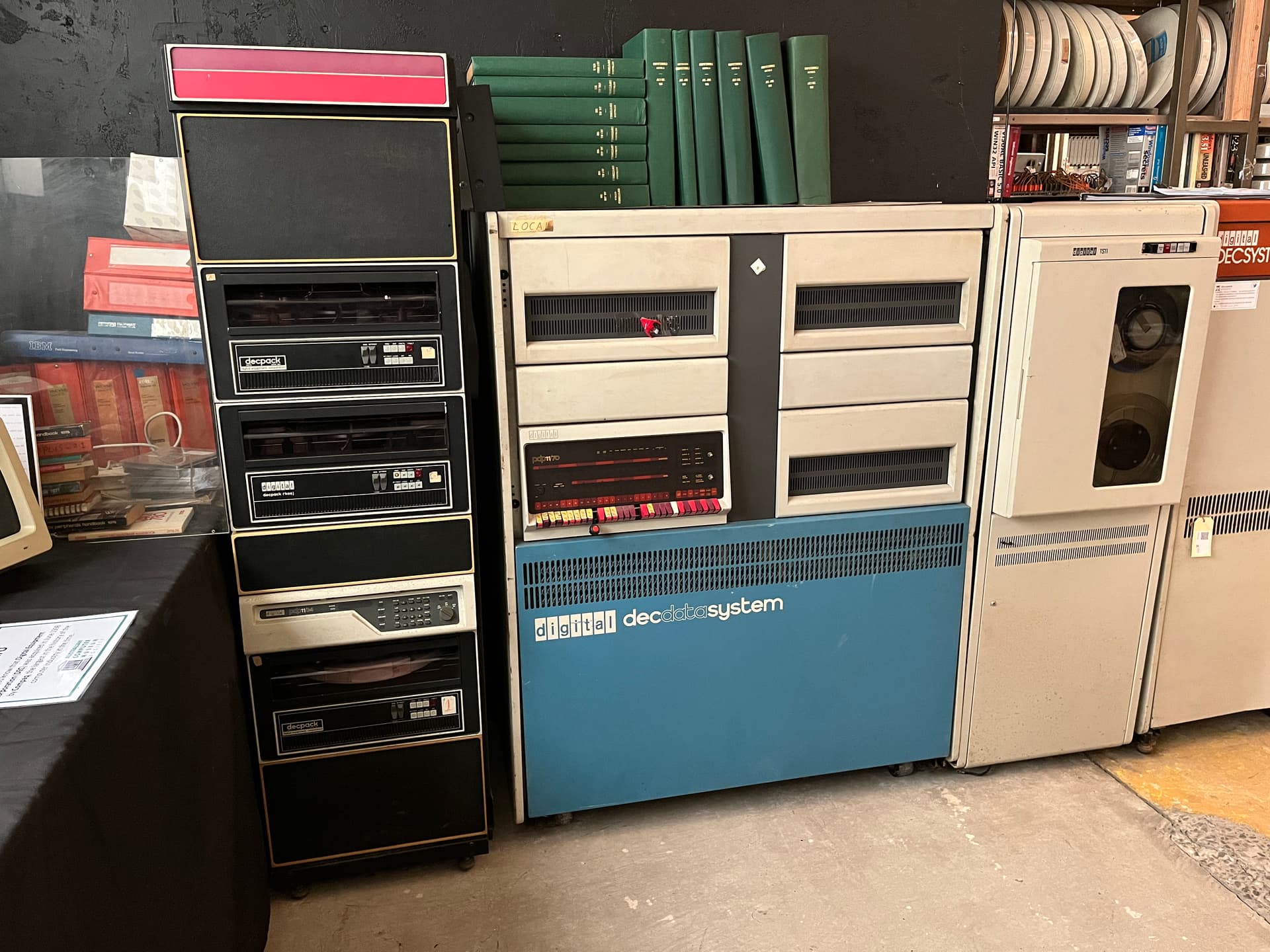
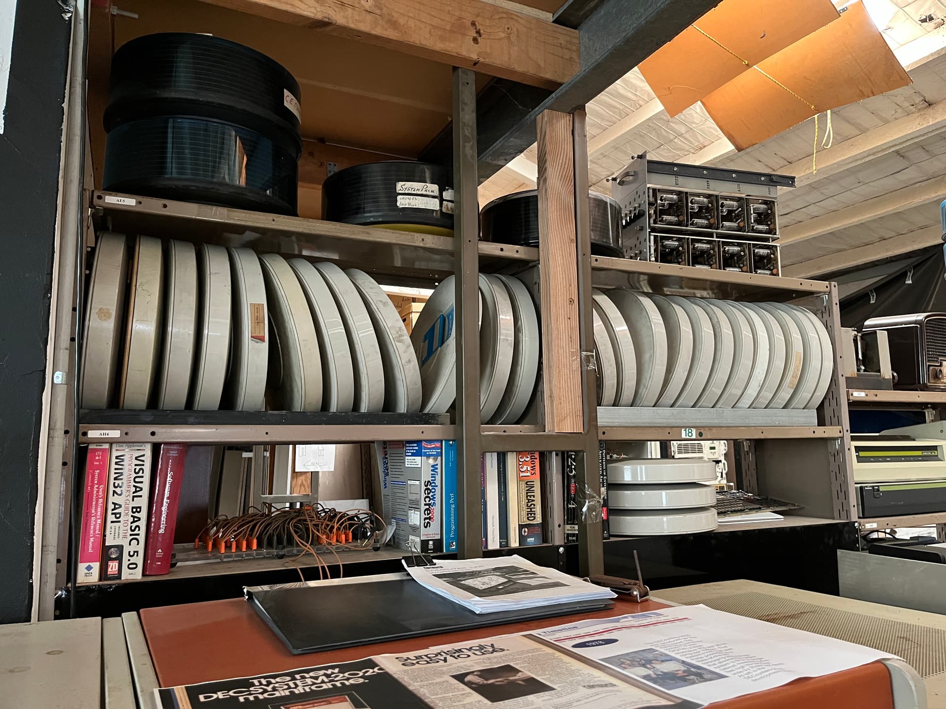
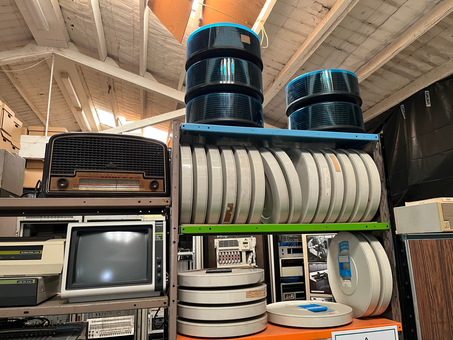
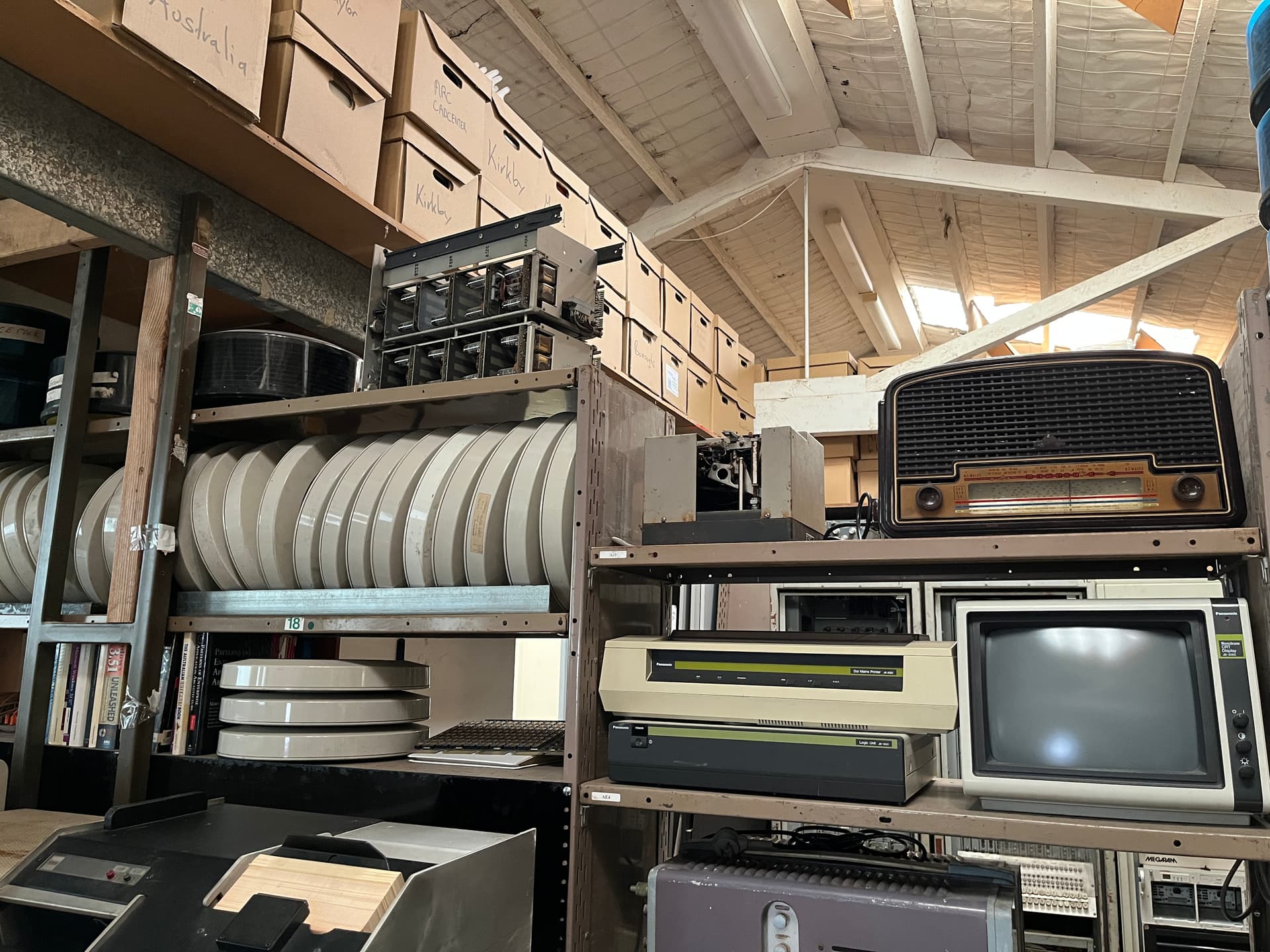
Judging by the size of these machines they were probably around before my parents met. Apparently those reels above the machines are in the MEGABYTES range which really puts things into perspective. Some of the following I’ve read about but never seen in person.
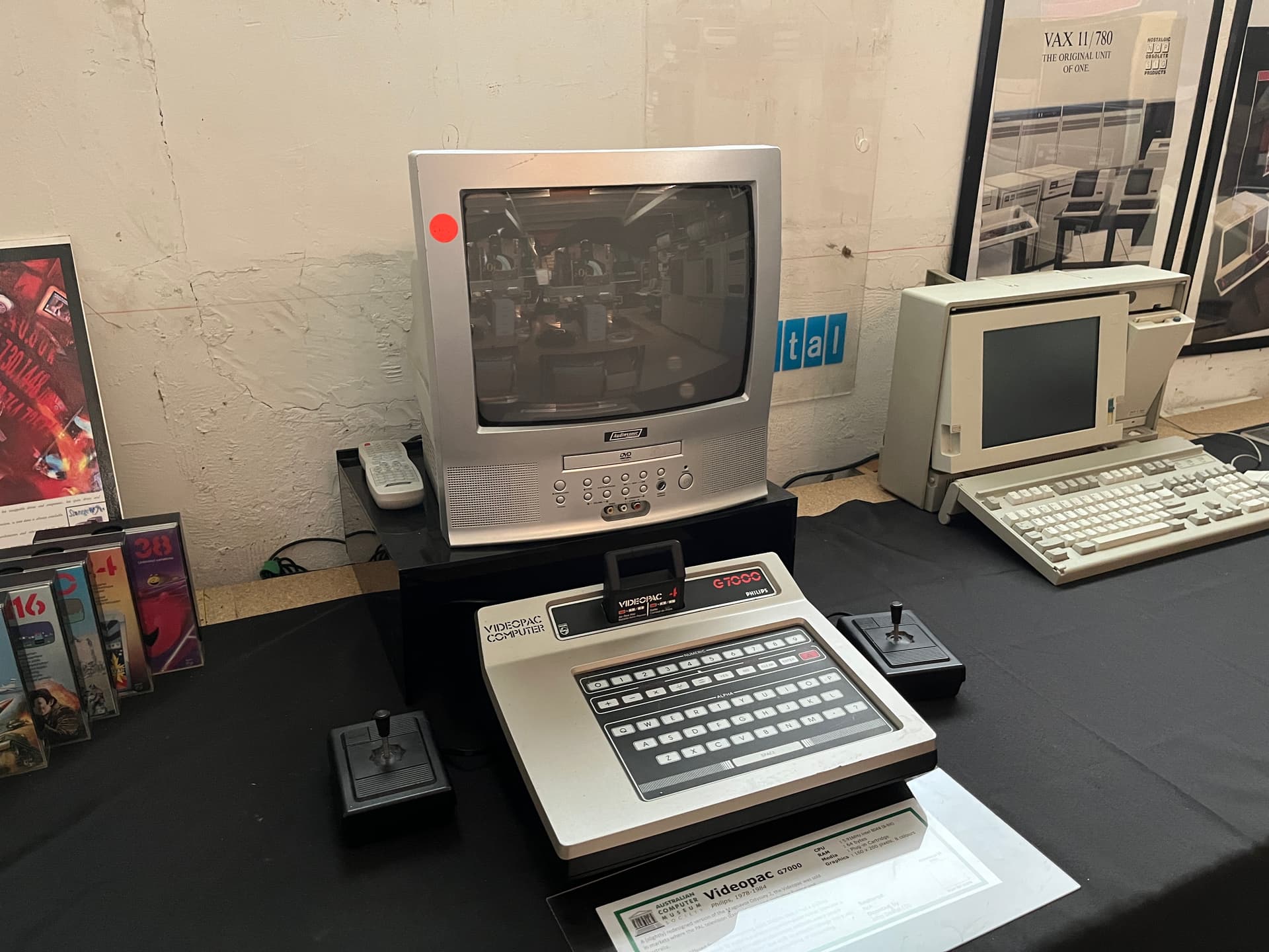
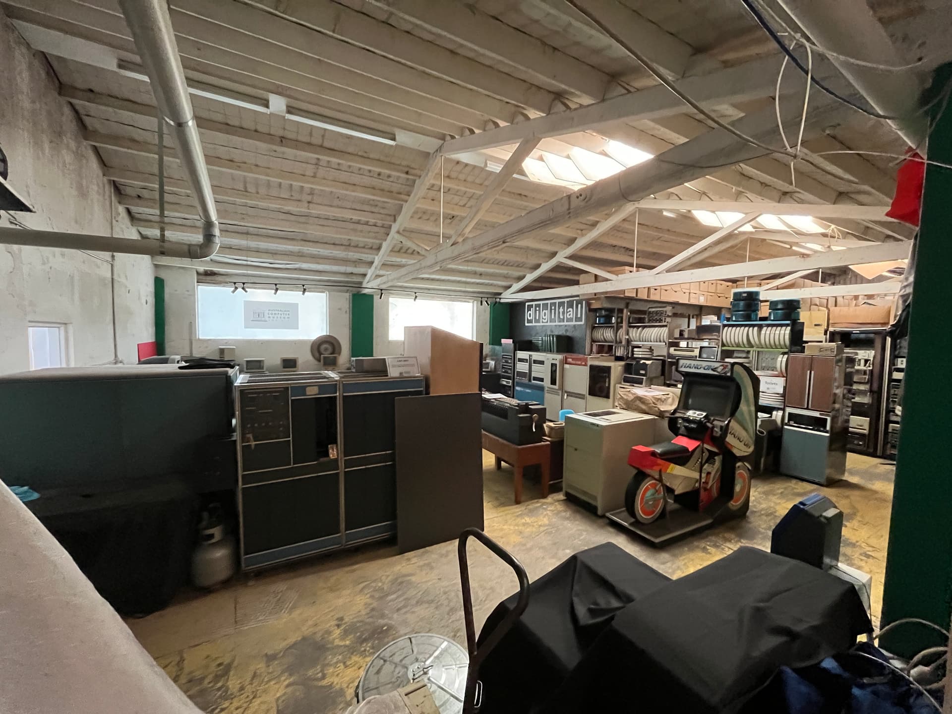
Looks like I’ve hit a limit on image uploads, I’ll do a second post shortly.
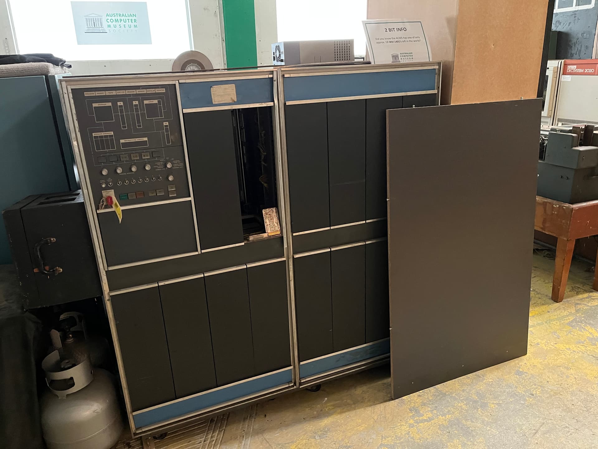
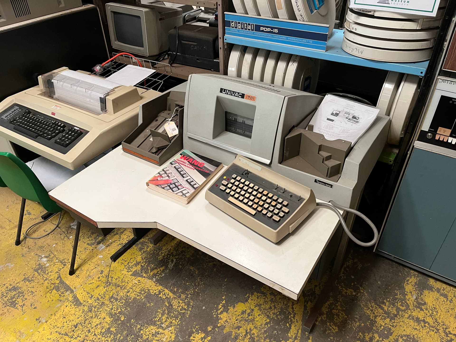
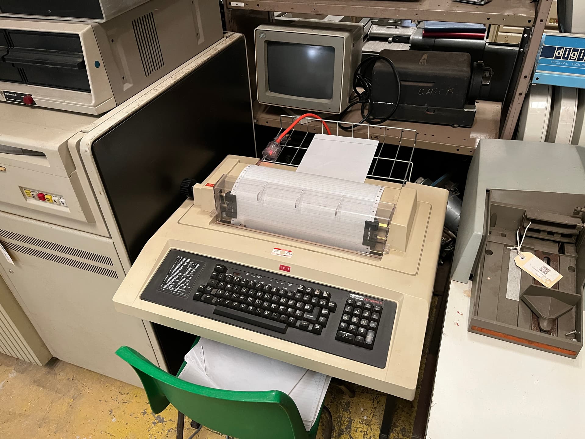
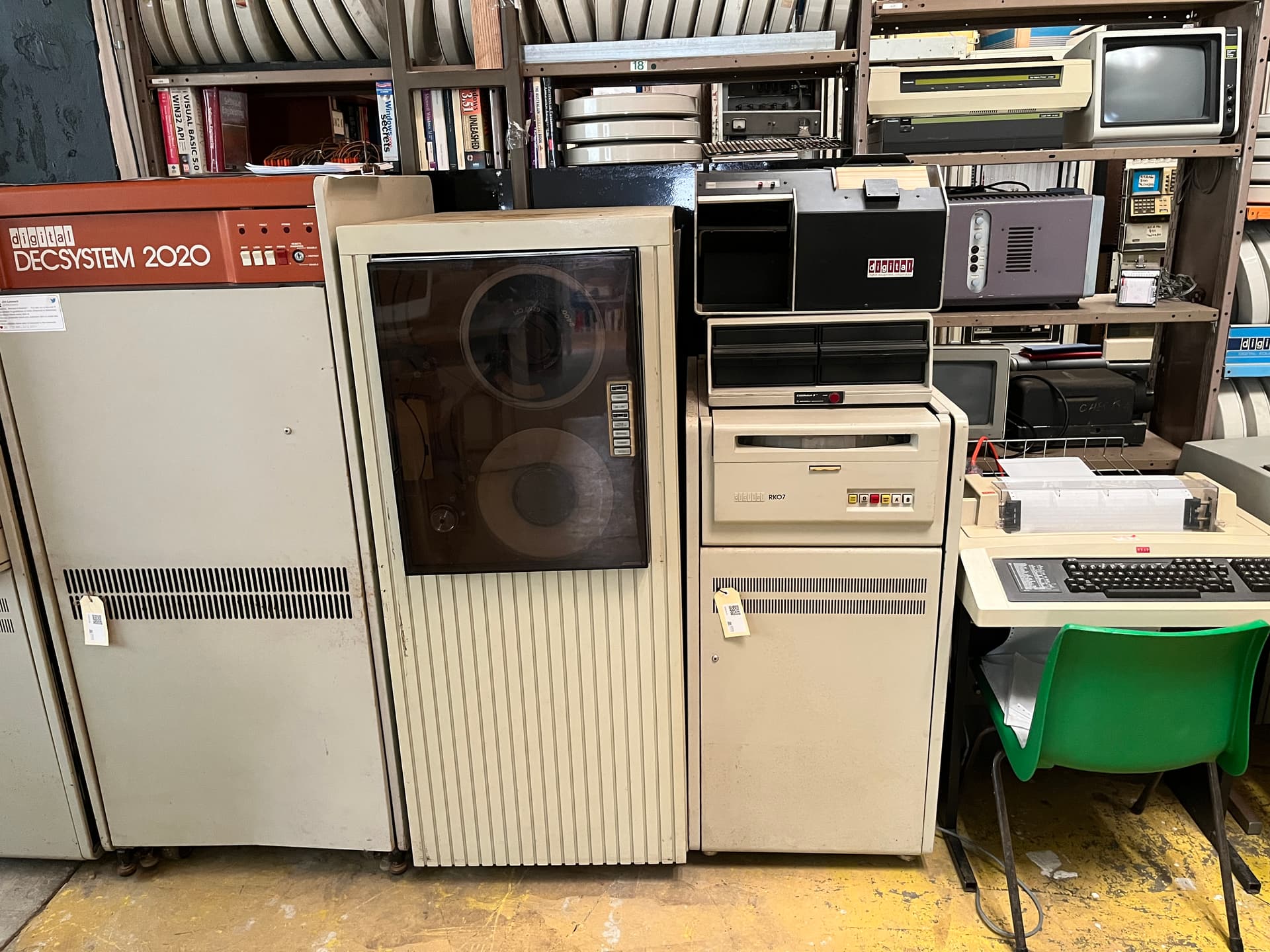
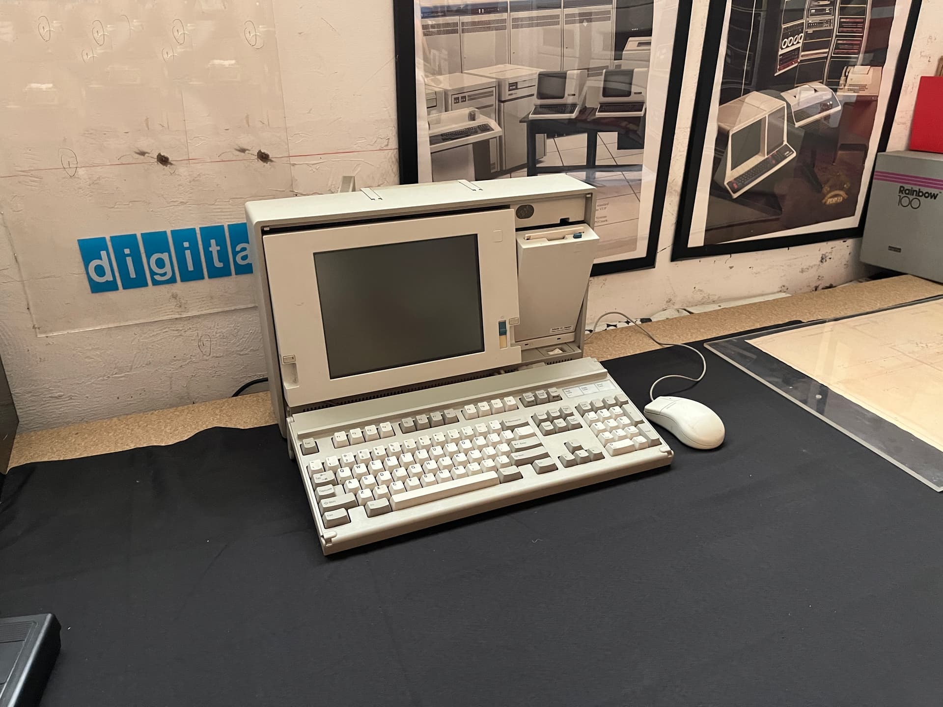
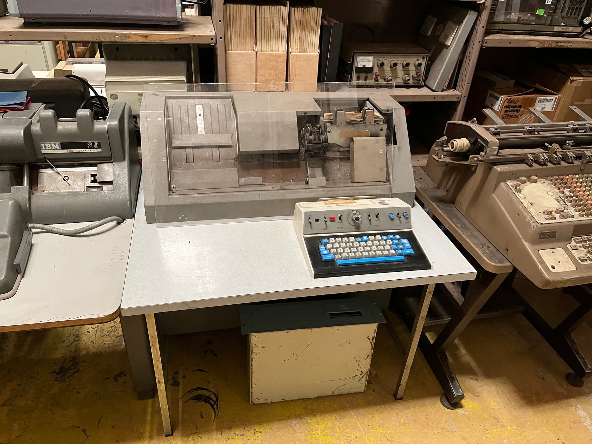
Here’s the second batch of photos. I didn’t get any of the gift shop, you’ll just have to visit to see what’s available I guess. ![]()

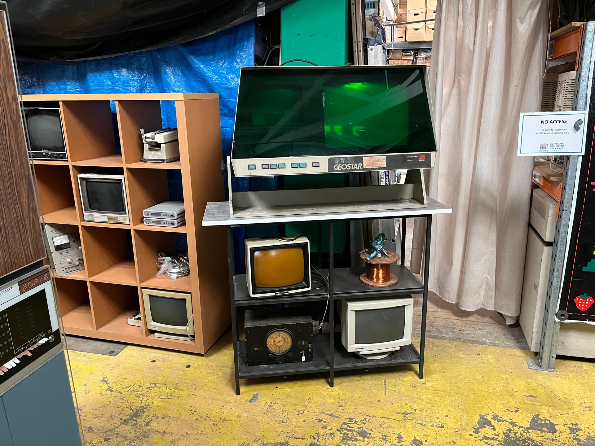
Nevermind all these PDPs, I’ll take two of the GEOSTAR.
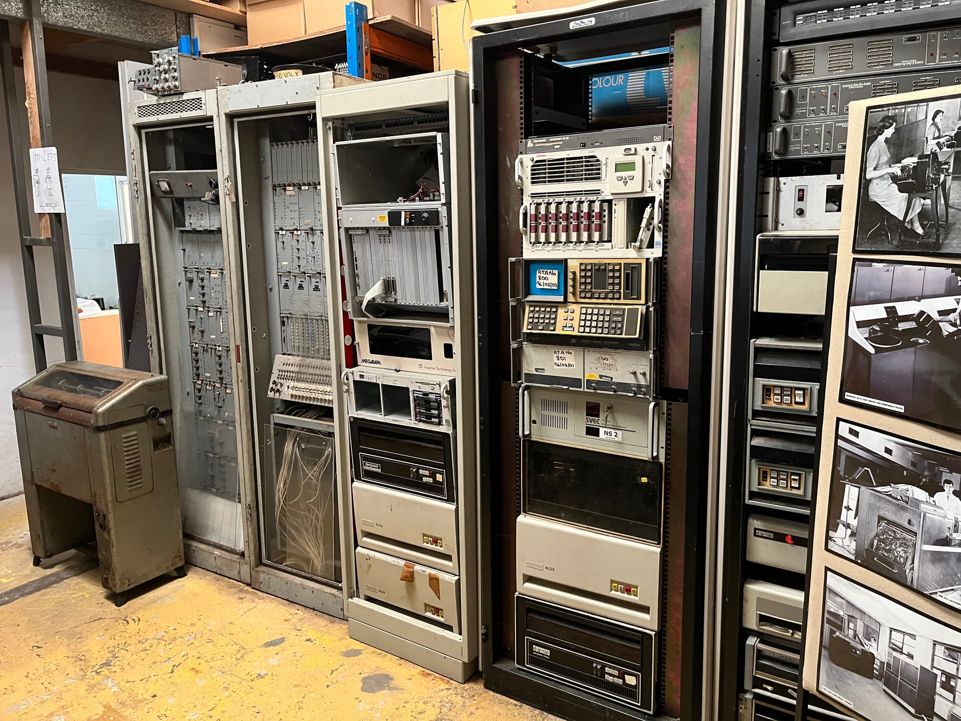
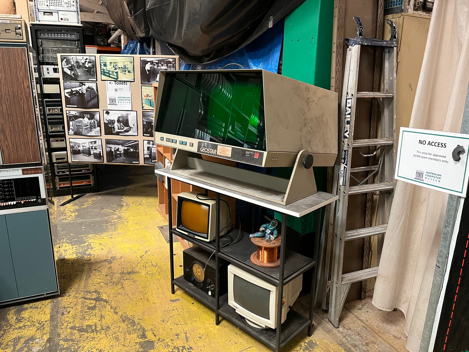
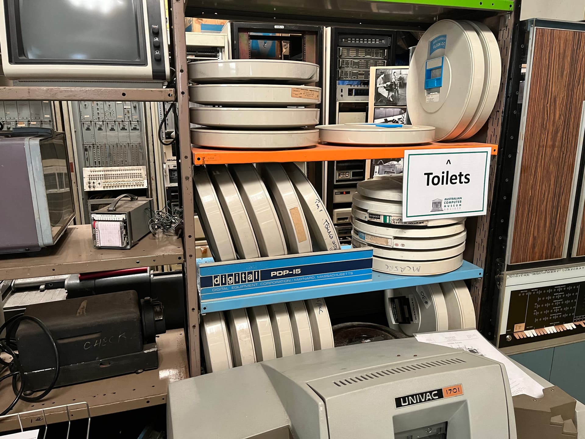
Good use of the racking here, sure are a lot of RL02 things.

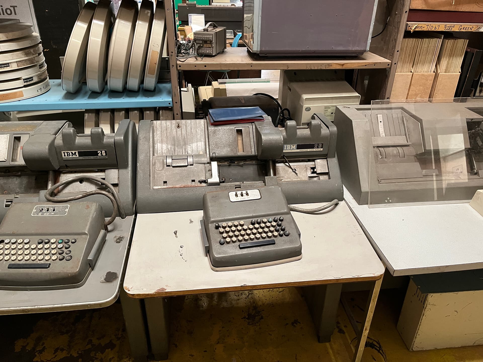
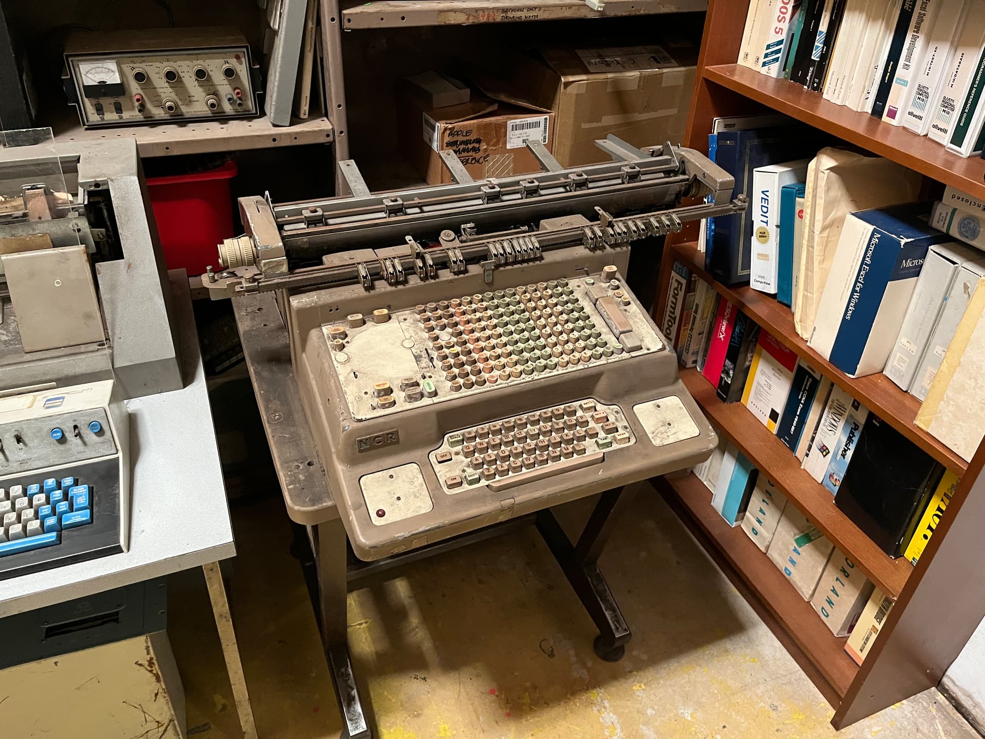
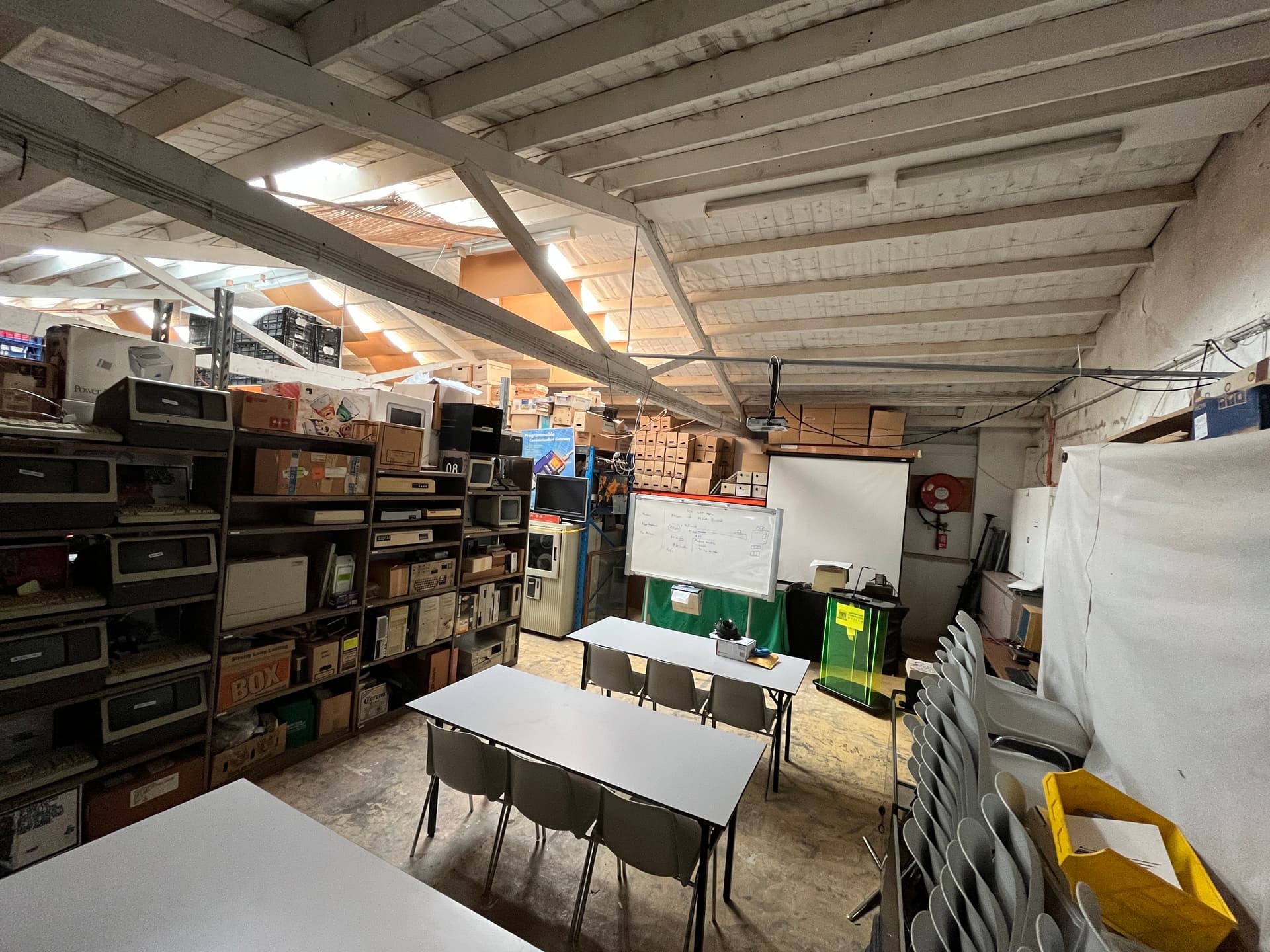
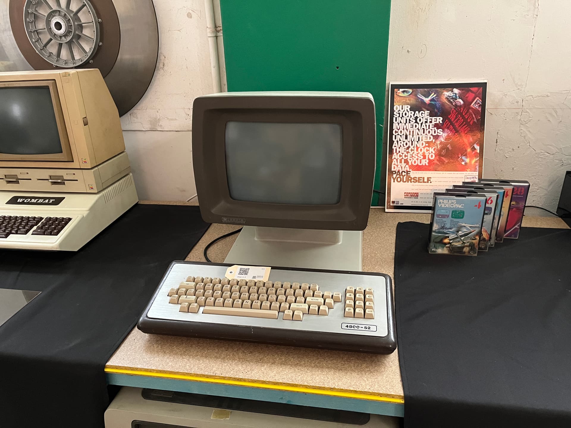
Some light reading to the left on that last image. My typing skills aren’t that good so I stick with dictation a lot of the time but I feel as though these might be pre-standarised AT keyboards came about.
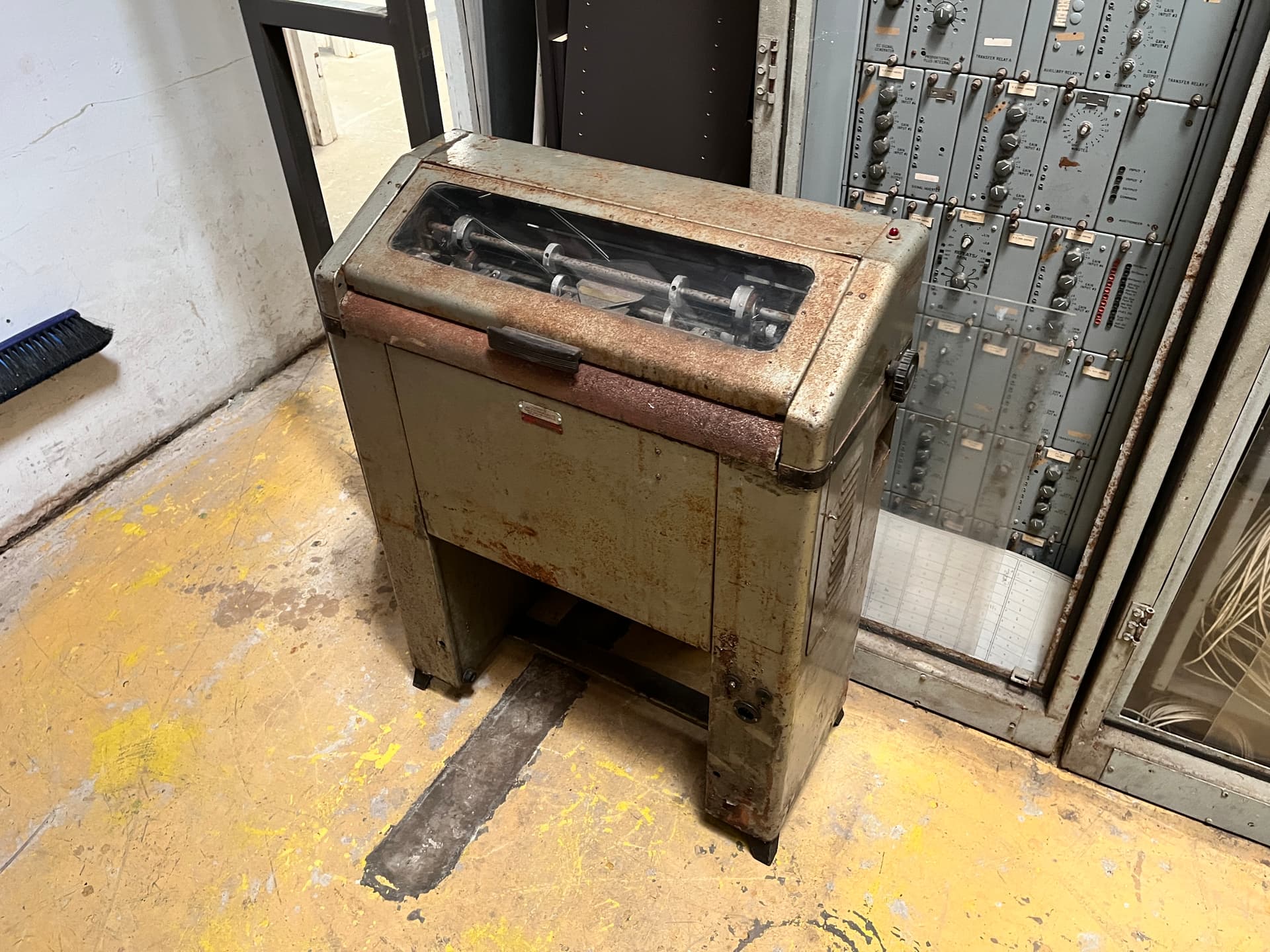
This might be an industrial shredder, or it might compute things - anyone?
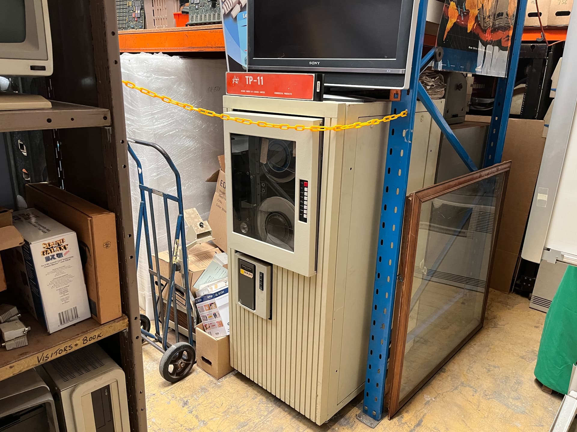
Obscured by a yellow chain we have a TP-11. I can’t tell you much about that because it is off-limits.

Keith looks to have stopped by here. He left his Marshall amp.
2 Likes
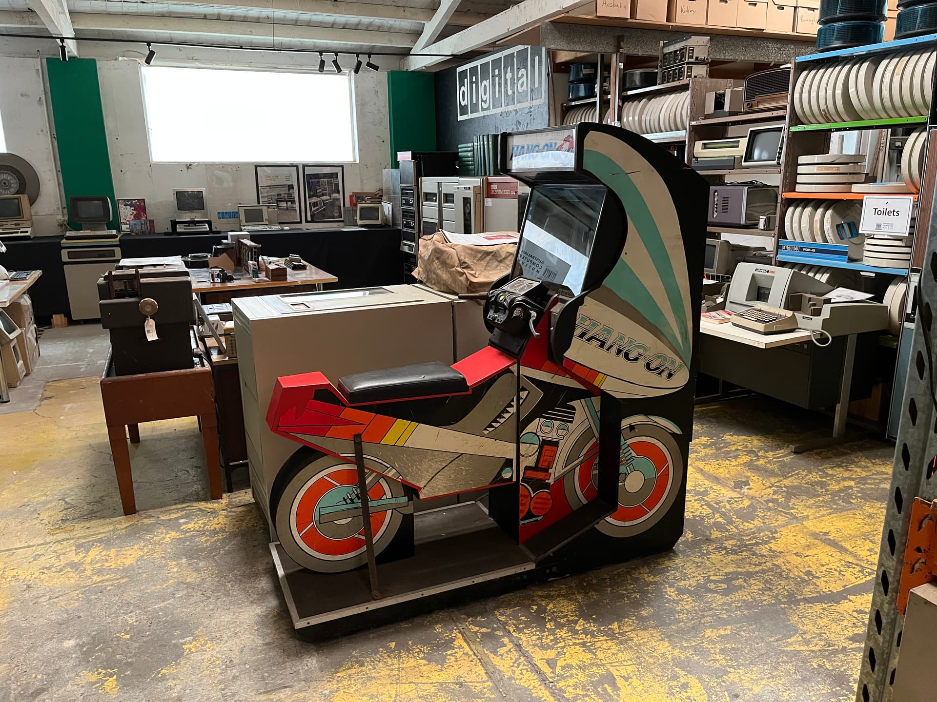
One more post before I hit the hay. I’ve always had a soft spot for arcade games and this one ticks the box.
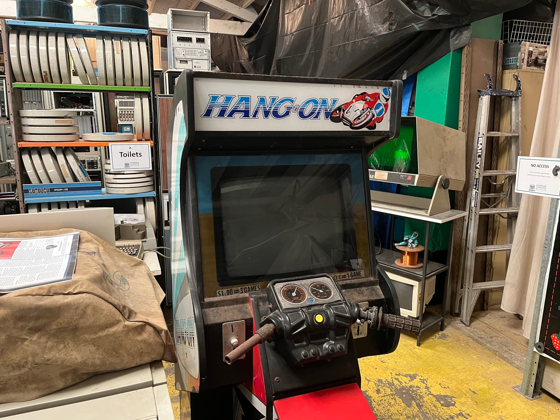
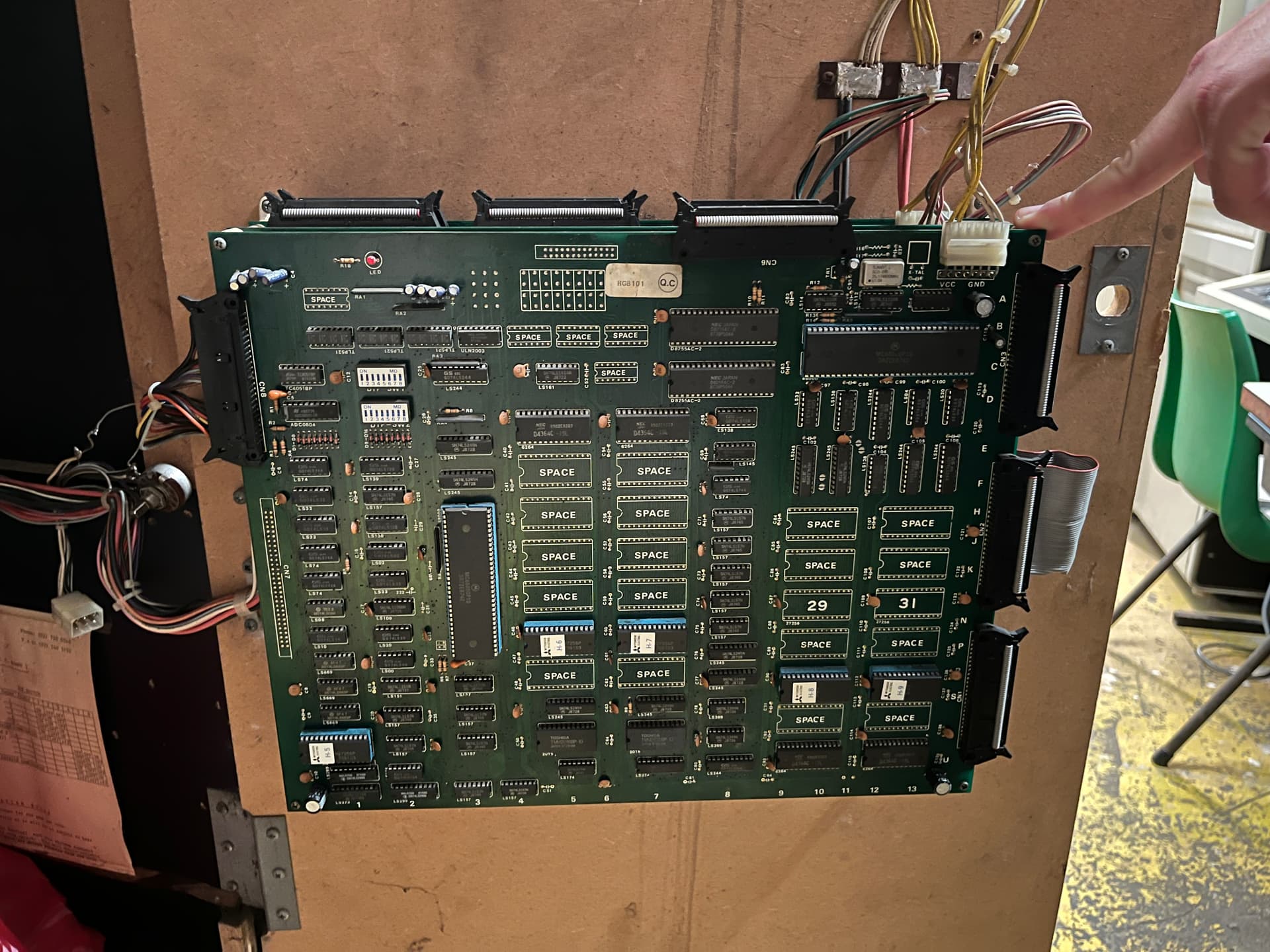
The board that lives inside. Then there’s this beast sitting near the doorway…
Incredible to think that some of that hardware is older than my me by a long shot.
I’m a DJ by trade, computers are just a hobby of mine, so it was quite exciting to find this many dials hidden in a drawer. I’ve loaned the microscope to @ShaneMcRetro and he said he’s doing some biology with so no doubt he’ll post soon with that.
3 Likes
Biology indeed. Here’s some stills from the microscope. @SuperNick you’ll get it back eventually.
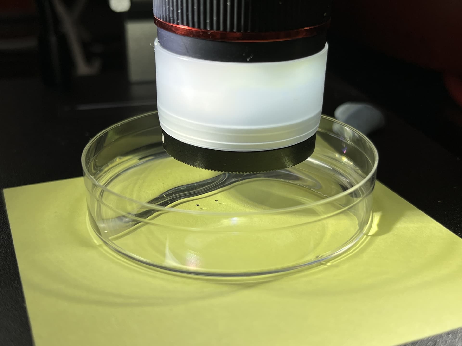
First up, here’s a photo of what was being recorded - I tend to use video so I can step through frame by frame.
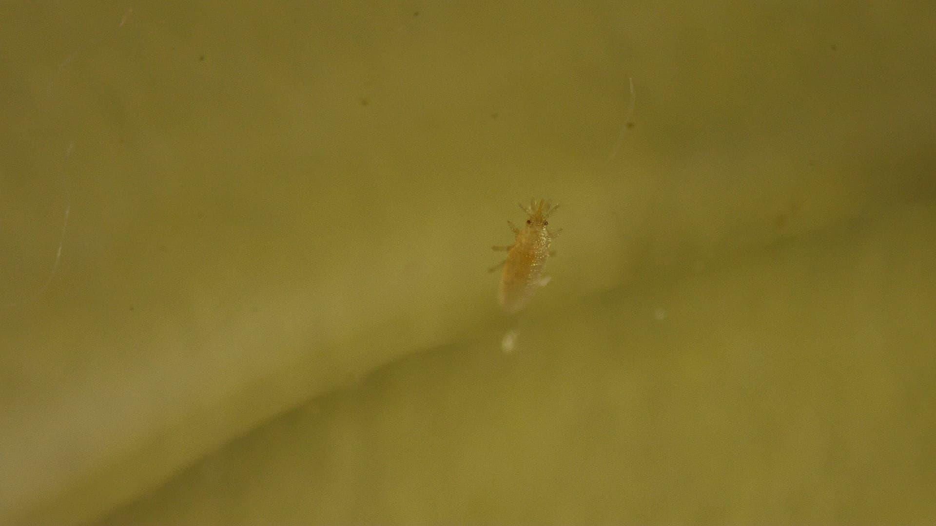
This little buggo measures around 1-1.5mm and I think he might be a thrip nymph that drowned in the water that was keeping the stick above the water line alive.
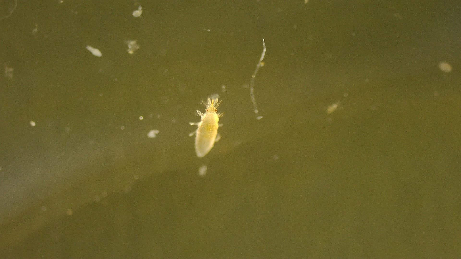
Those other white things to the immediate left and diagonal left of our deceased thrip look to be rotifers. They were definitely alive too!
Most rotifers are around 0.1–0.5 mm (0.0039–0.0197 in) long (although their size can range from 50 μm (0.0020 in) to over 2 mm (0.079 in))
So the resolution of this is quite incredible. When I slap a dessicated cicada underneath it for example we see…

An incredible look at a floury baker cicada’s compound eye. It’s eyes are red instead of the typical brown/grey due to the way it died, crawling up a wall in the hot afternoon sun.
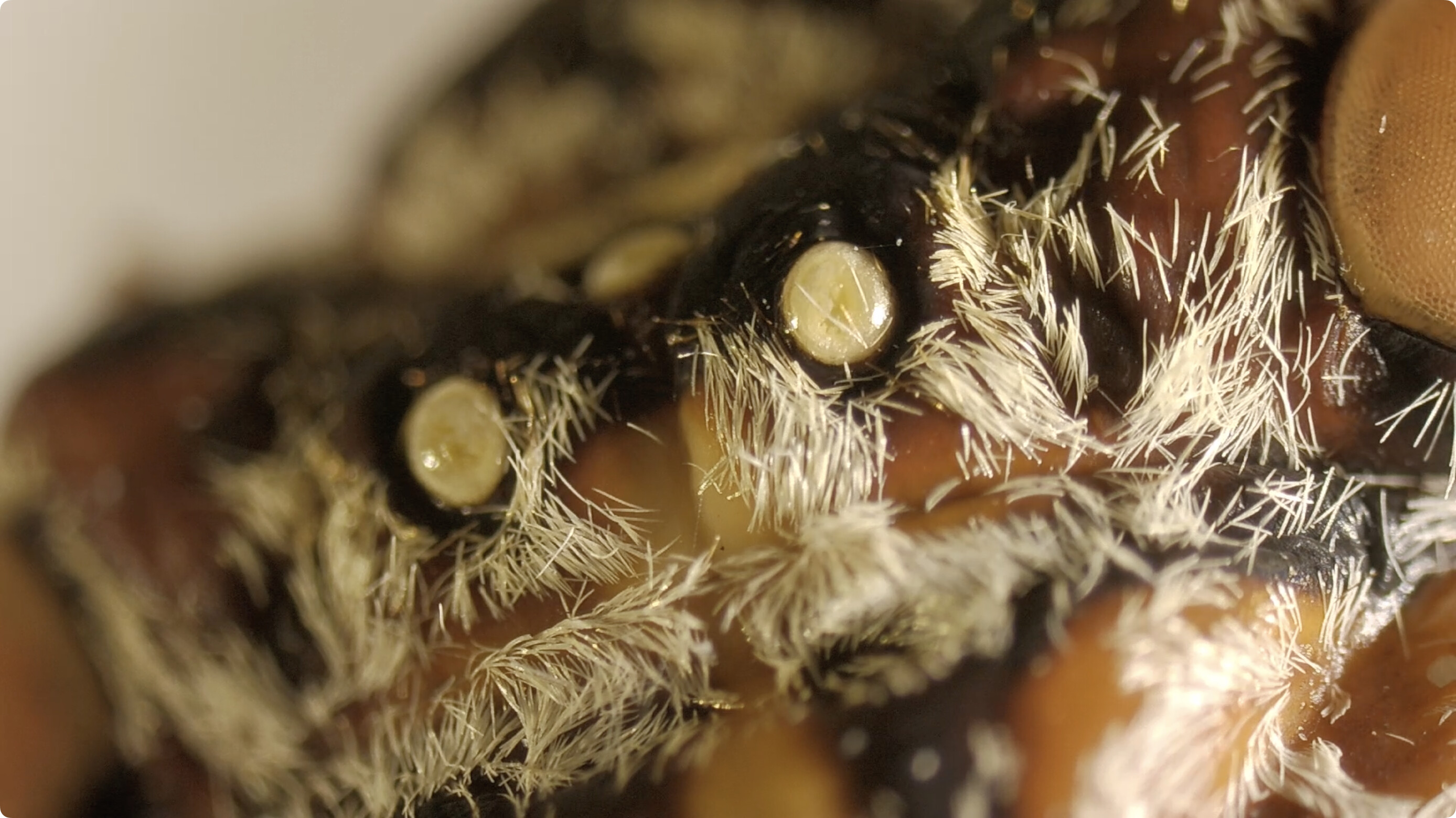
The ocelli, or simple eyes, are very visible as are the filaments (hairs) covering the cicada. The neatest thing about this specimen was the way the abdomen broke off when it fell off a book case on a window day - it exposed the noise making muscles!

For reference above is how the male cicada makes noise thanks to time.com
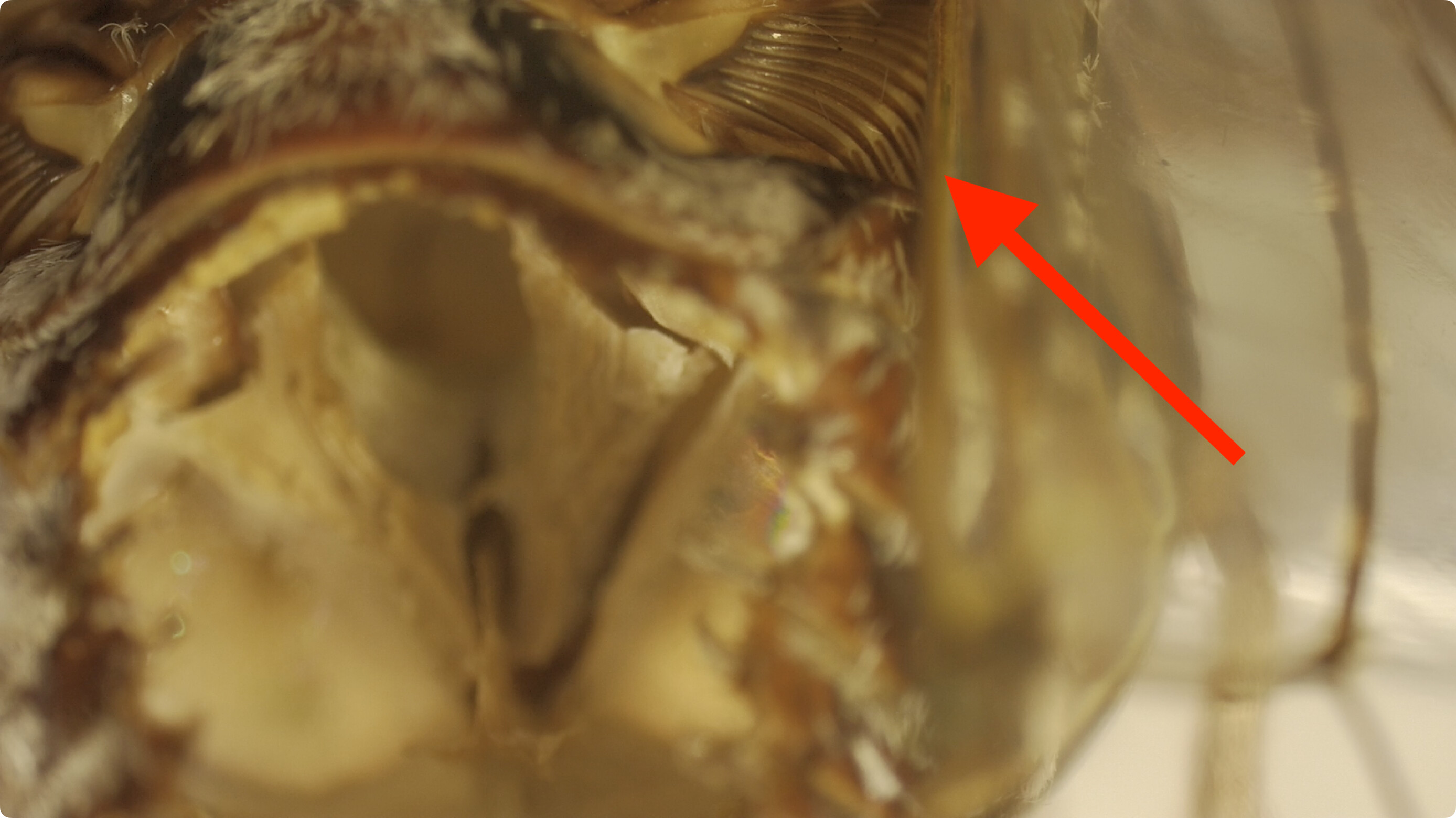
This was taken from the rear of the cicada. Here’s the tymbals, they are the ribbed structure.

And the muscles attached to the tymbals. Honestly never thought I’d have a chance to see these up close with a microscope let alone at all as they are internal.
Overall though a very neat microscope - probably good for other things like board repair but I have a deceased Endoxyla encalypti which is somehow bigger than the cicada to look at next. You’ll get it back eventually @SuperNick
3 Likes
Well that’s one way to use the microscope I guess. Here’s some more information I found while clearing up my desktop today on the Dasher 386-25K. Some of these might be above but I thought I should put them all up before they are purged from my desktop.
AT Power Supply Pinouts
Source 1
Source 2
Keyboard Related
Source 1
Source 2
Mystery DIP bank? Related to Baud Rate?
Source 1
Source 2
Troubled Capacitors - Rob’s Comment
Source 1
Testing Keyboard - Does it match older display terminals i.e. Dasher D411 and D461 from 1986.
Source 1
Potential Replacement SIM Slots - Might be wrong type
Source 1
Backup Power Supply Options
Source 1 - Started here.
Source 2 - Led me here.
Source 3 - Ended up here.
Dumped ROMs
Source 1
Source 1 - Alt.
And that leaves that where I’m happy with. As I’ve said before I hate working with AC voltage but was able to do so this time without getting any shocks or zaps. That doesn’t mean you should though.
AC voltage can kill.
Thank you to all that helped along the way, including the ACMS for having a RetroChallenge prize to help motivate me to get into this. Maybe I’ll see you all again this year. Until we next meet! ![]()
1 Like