Finally I have been getting into the hardware. Cleaning the chassis and refurbishing the punch is up first.
Apology: It would seem that I can post my facebook videos but when I try to post the link for a set of photos from facebook it just puts up the header for my FB restoration page. This is annoying for me as well as for others I suspect.
I can’t turn back now sorry. lots of duplication so that it is up here in the forum.
With the front panel removed you can see the reader mechanism and switch block. The reader will be serviced later
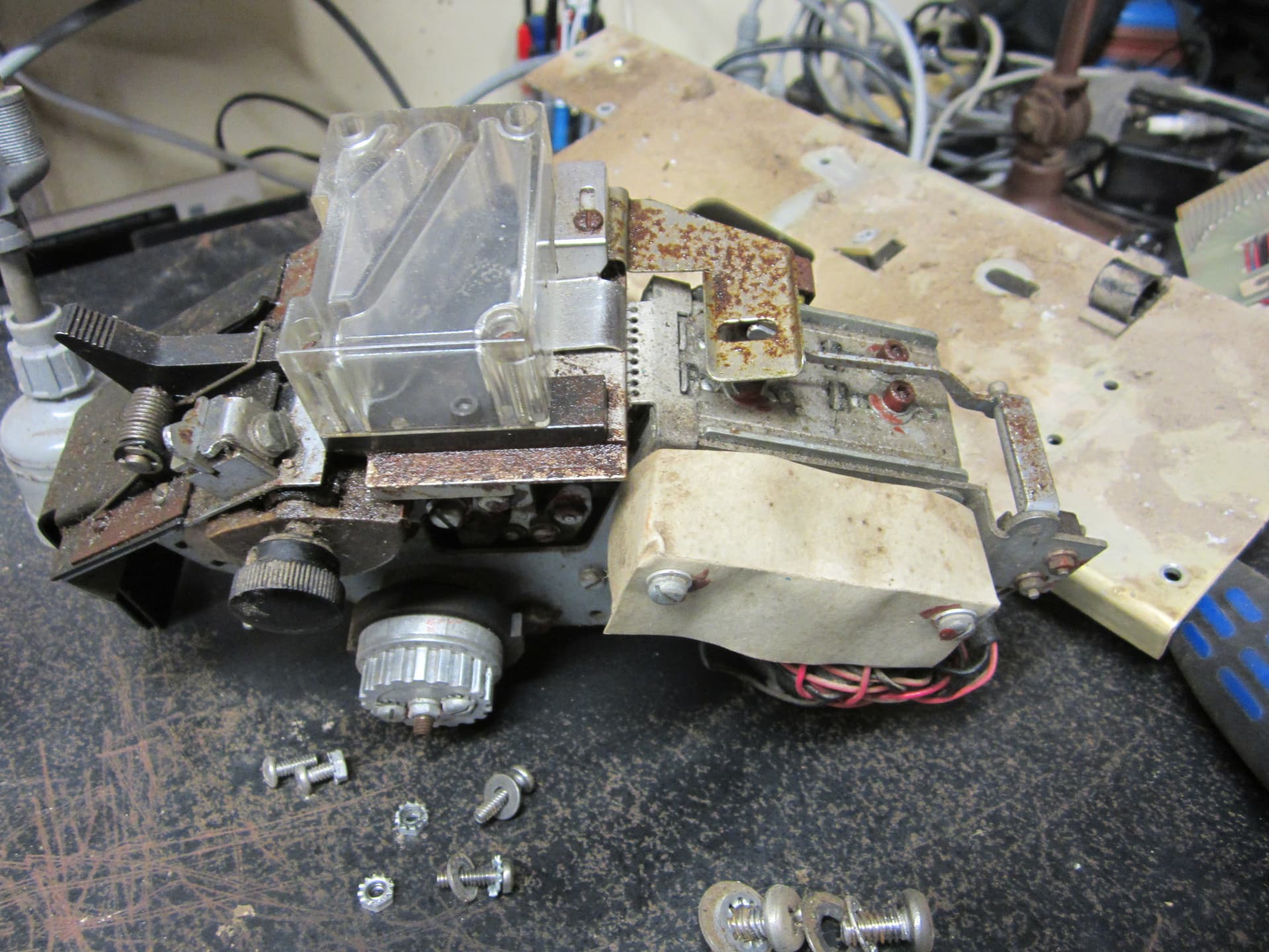
With the punch removed it can be serviced. This will be shown in detail in the next video
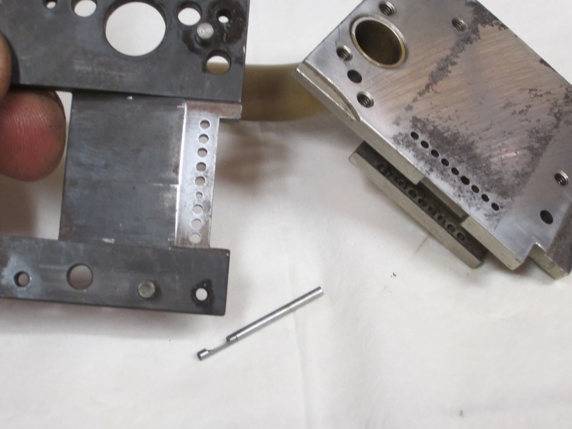
One of the most important parts of the punch are these components. The die block, the punch pins and the one on the left which is the anvil for want of a better word. The anvil surface is finely ground and very precise so that clean holes are punched. In the case of mine it was a little rusty but came up well after honing the surface with an extremely fine oil stone.
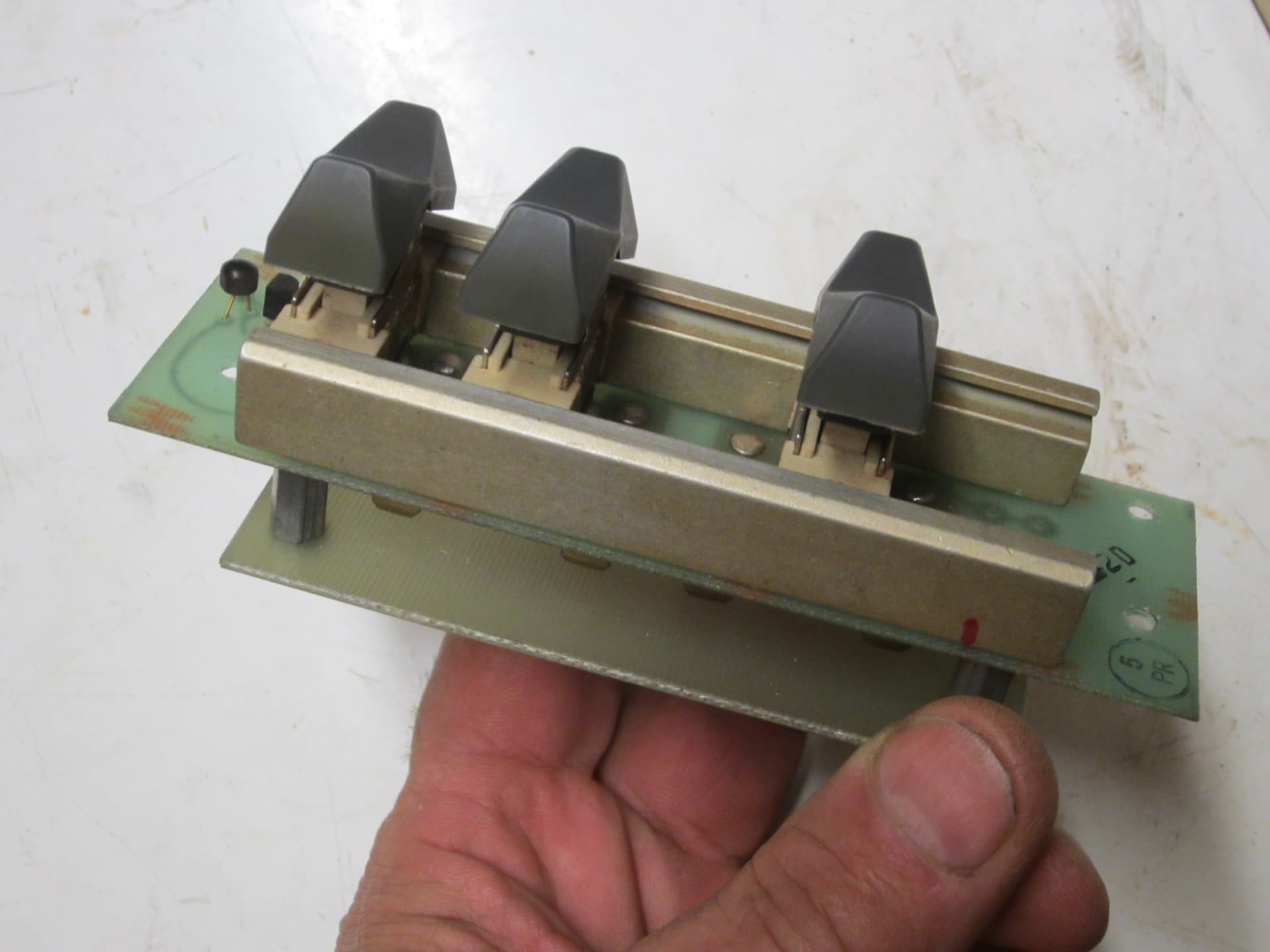
The switch block had to be removed and the switch tops also removed so that I could straighten all of the metal parts. This punch must have been dropped or hit hard enough to bend them.
Here it is looking a lot cleaner but not yet ready for testing
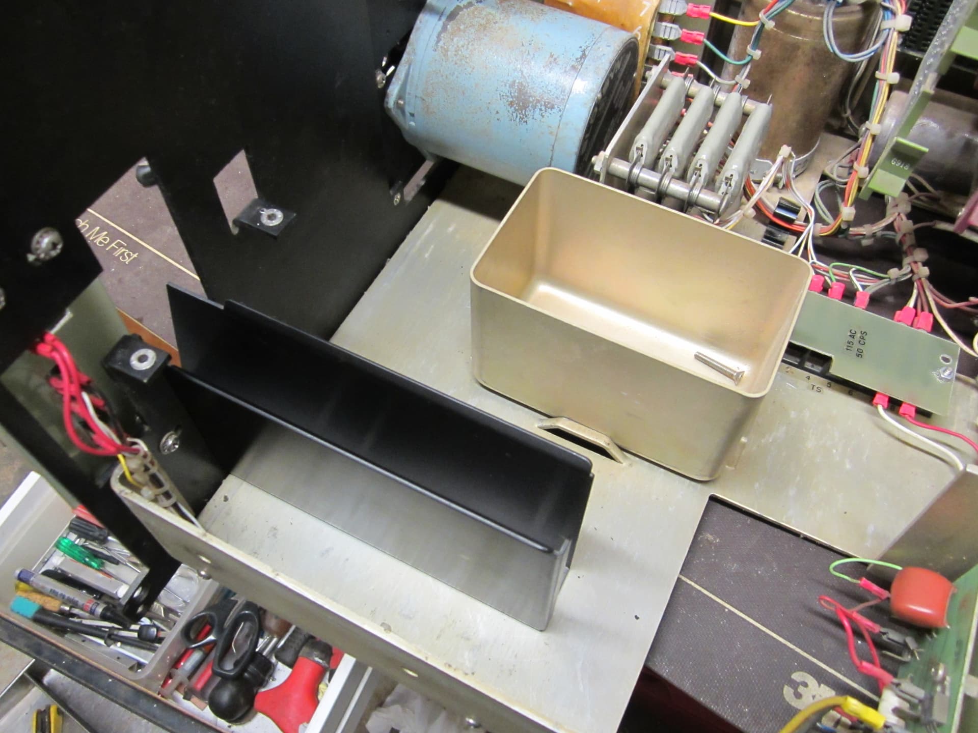
The paper output guide was too rusty so it was wire brushed, sanded and resprayed. It will be the first of many.
This is the refurbished punch ready to go in. Watch the next video to see what was done.
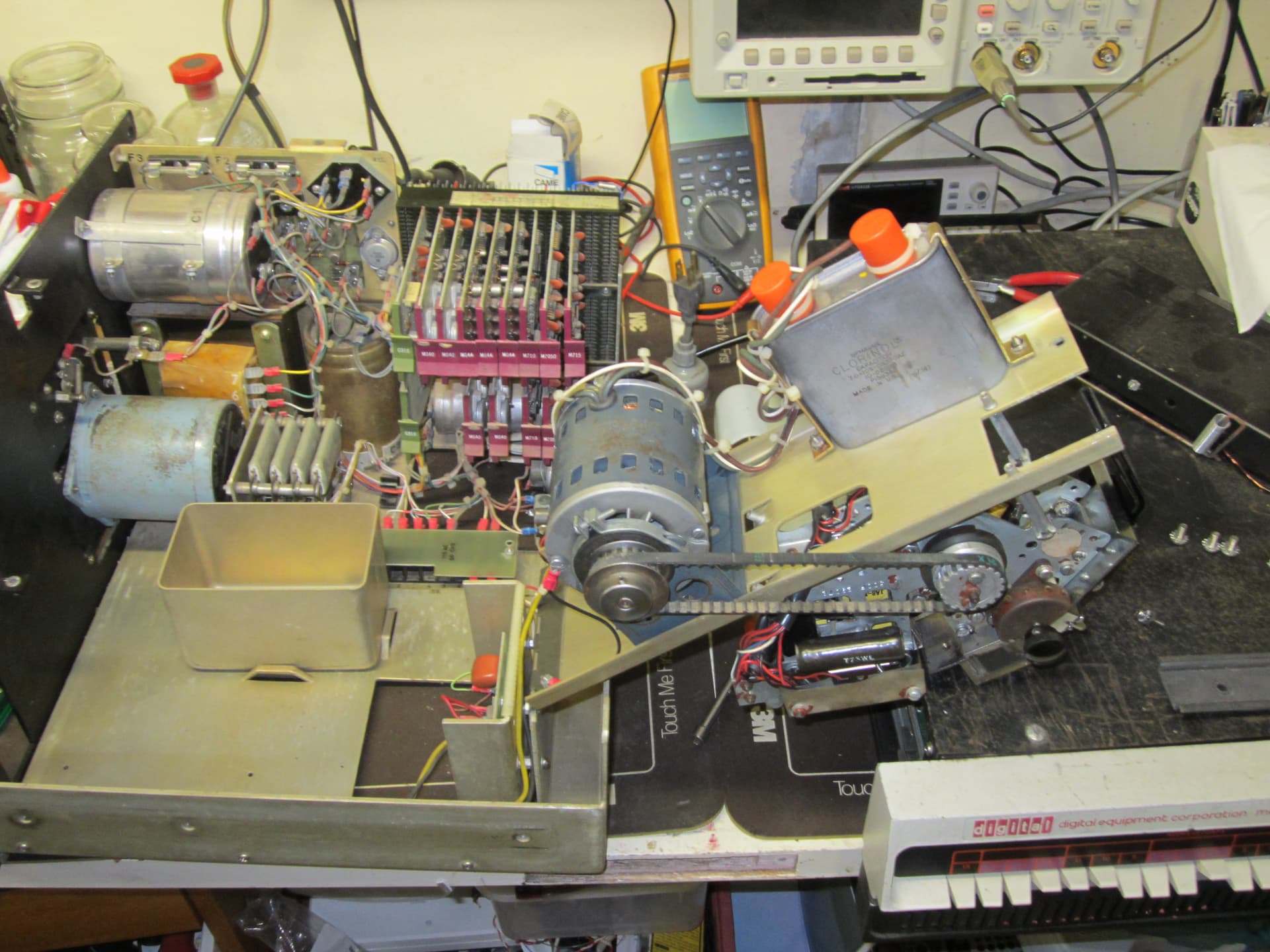
The punch is installed but there’s more work before testing.
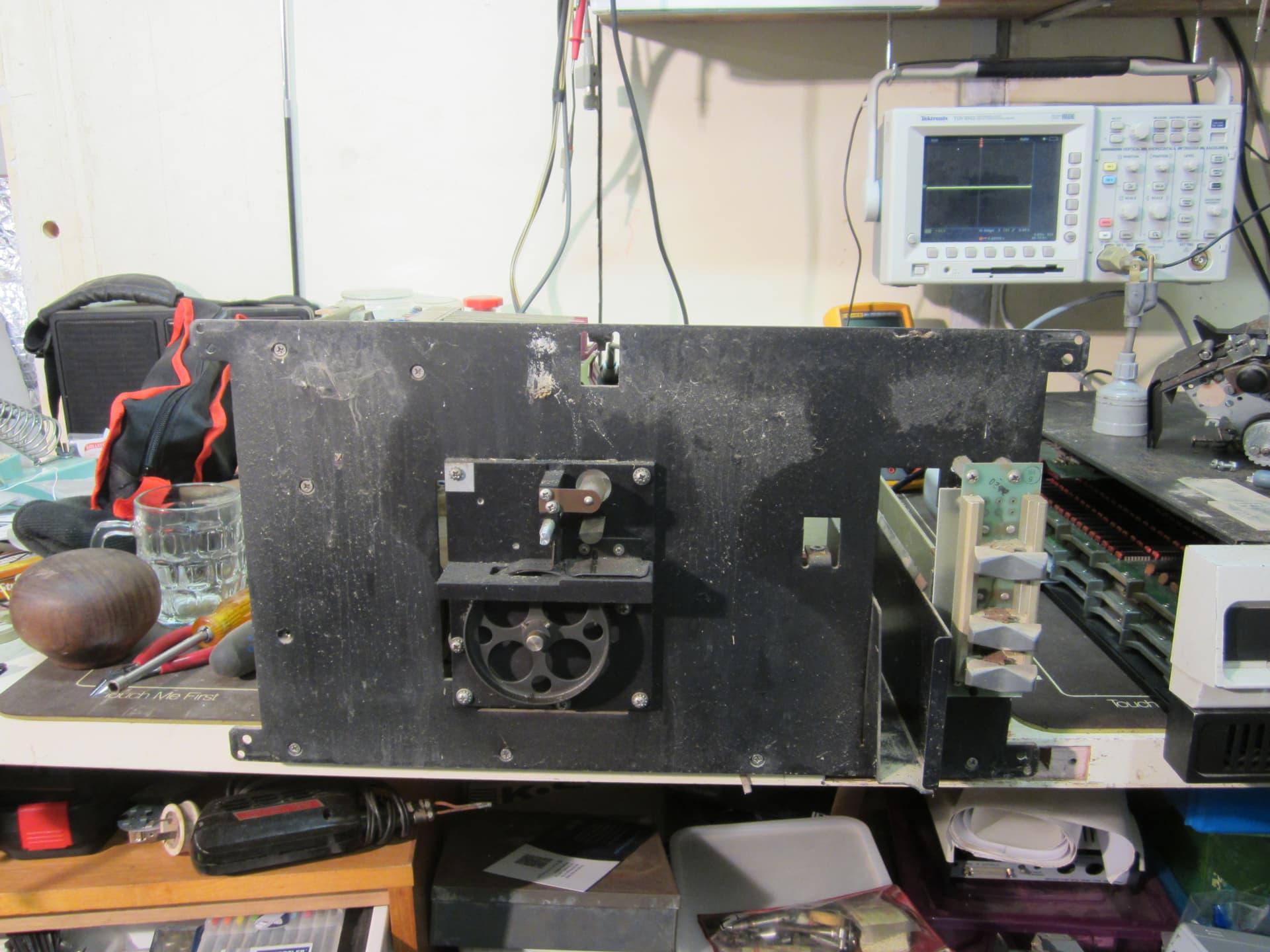
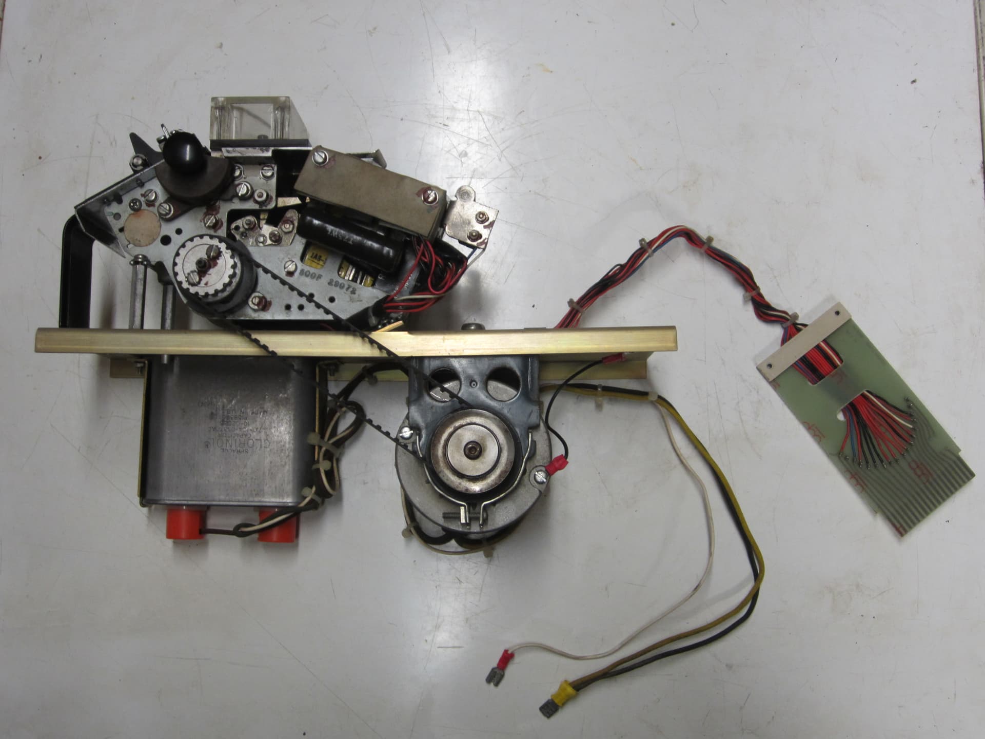
With the punch mounting plate flipped out you can see the drive motor and phase shift capacitor for it. It is important to note that this capacitor may have PCBs (Poly Chlorinated Biphenyl) oil inside it. PCB is a known carcinogen. If there is any evidence of leaking you should take great care in cleanup and replacement of the capacitor. Mine is clean and not leaking

That looks so much nicer.
The Chassis came up looking good despite the anodising being eroded in places.
Under the punch mounting plate hides this board which the logic board signals to turn the punch motor off and on. A low voltage side has a transistor driving a reed relay which provides electrical isolation. the reed switch operates a Triac to switch the 110V AC line. Watch out the power for this diverts through the front panel switch board even if there is no punch switch present