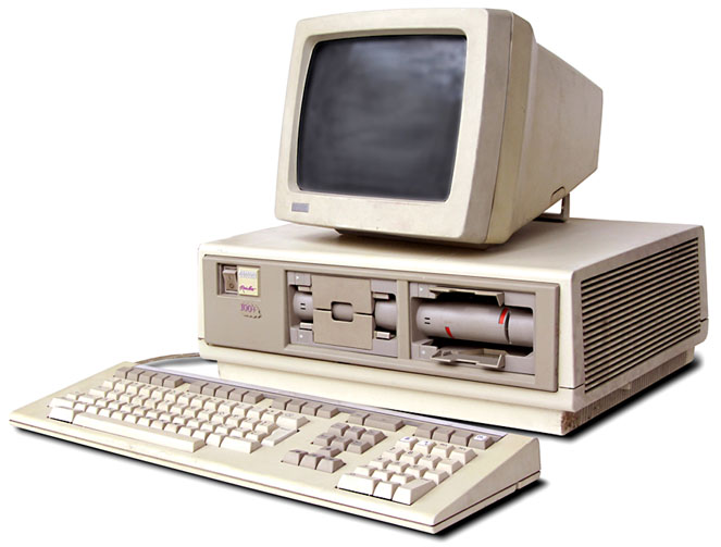
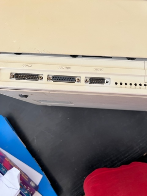
The Rainbow 100 introduced by DEC in 1982. This desktop unit had a monitor similar to the VT220 in a dual-CPU box with both 4 MHz Zilog Z80 and 4.81 MHz Intel 8088 CPUs. The Rainbow 100 was a triple-use machine: VT100 mode (industry standard terminal for interacting with DEC’s own VAX), 8-bit CP/M mode (using the Z80), and CP/M-86 or MS-DOS mode using the 8088 and that’s what make it very interesting.
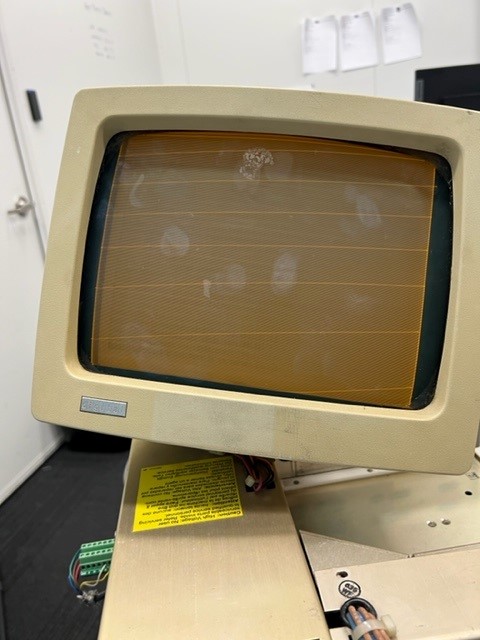
This is what it is supposed to look like
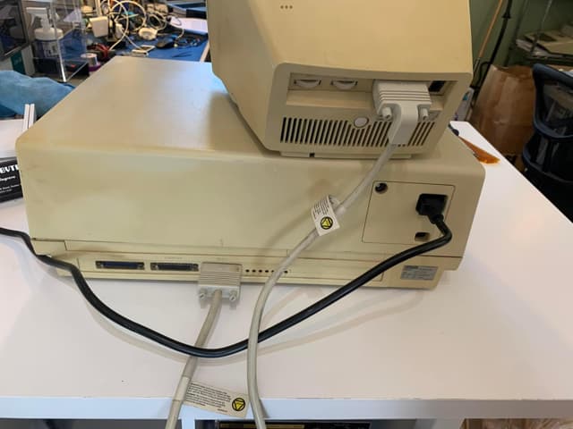
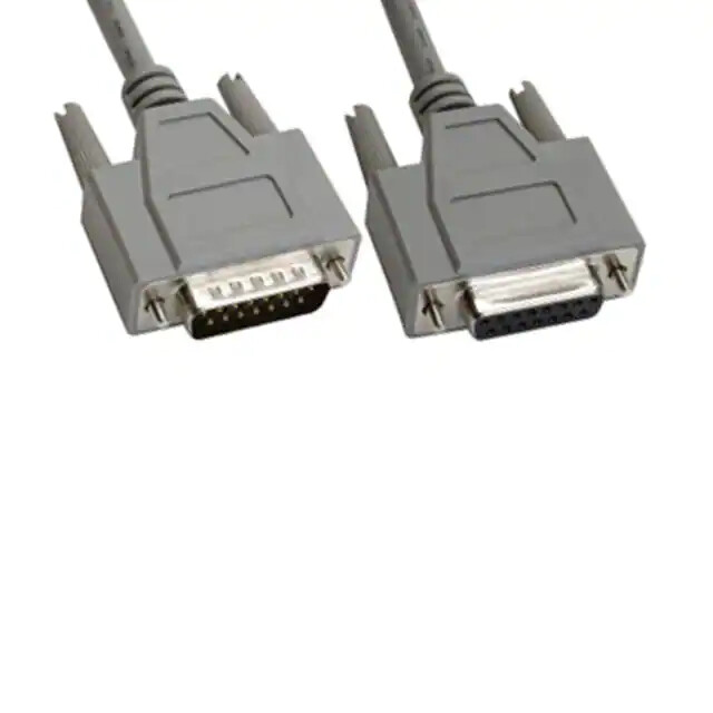
Do you have any documentation on these cables / connectors? You need the pinout of both ends.
The cable may not be 1 to 1. There may be some crossover pins. RS232 cables were often not 1 to 1.
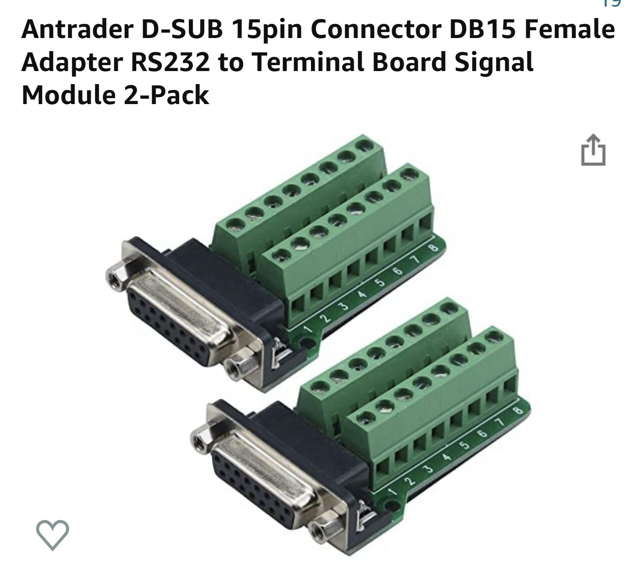
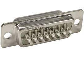
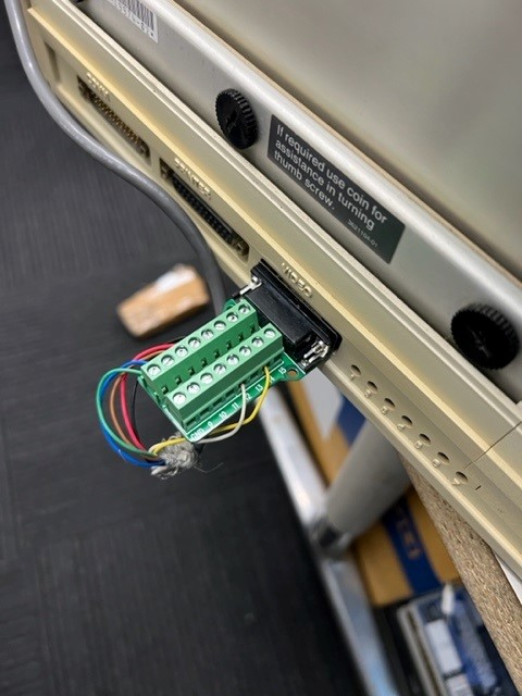
The connectors you have are for prototyping.
So if you’re just trying to work out the right connections then these are good
But for a long term installation you need the cable solder type with the back shell.
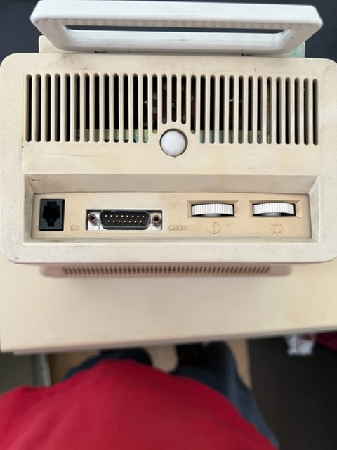
Your cable is for video and keyboard. You could take a chance and try 1 to 1. But if the cable carries power and it is not 1 to 1 then you could damage something. Connecting outputs to outputs or RS232 ±12V to logic signals could also be a problem.
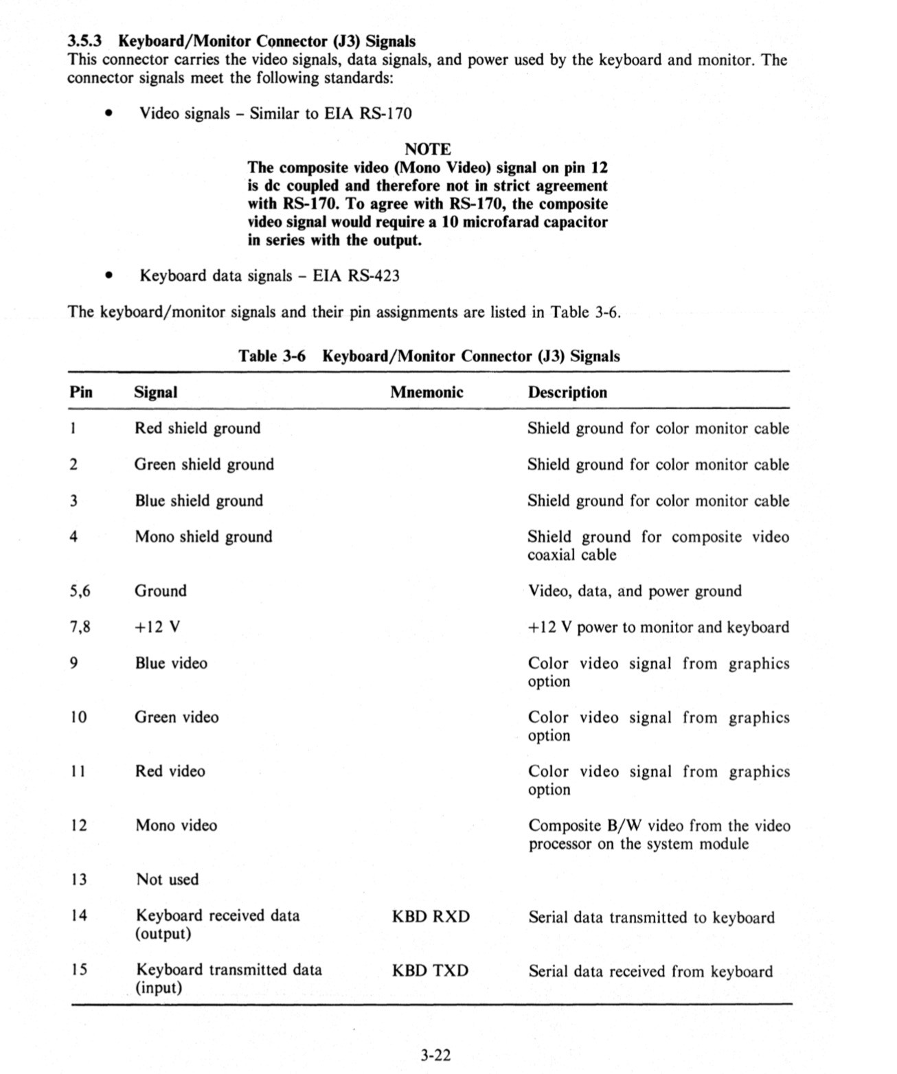
I have below the cable pinouts for all Cables that were made. The one I need is the BCC02 Mono cable.
If read the pinout correctly I only need to use Pin 4,5,6,7,8,12,14,15
Your right on the power as Pin 7,8 are +12v as it seems to provide +12 on both pins for the Monochrome version whilst pins 5,6 are the grounds with pin 5 is only for the monochrome version and pin 6 is ground for the keyboard.
I am planning on using this as a prototype tool and then create a real cable but my soldering skills on a cable pinouts are horrible. I find they are the worst to try and solder correctly.
Having the manuals makes a huge difference. You’ve pasted section 3.5.3 J3 signals.
This looks like a 1 to 1 cable.
Pins 14 and 15 to mention input / output, but being RS423 I don’t think it would damage anything if they were accidently reversed. Have a look at RS-423 - Wikipedia
The DSUB connector should be relatively easy to solder using the “bucket” / solder cup type.
Ok finally back to it.
I had tried to get the cover off and it was stuck.
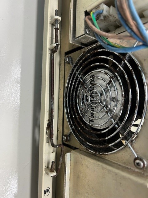
I finally managed to get the cover off and discovered the left side latch was stuck shut.
It needed some WD40 to release it.
Check out the rust on the release latch.
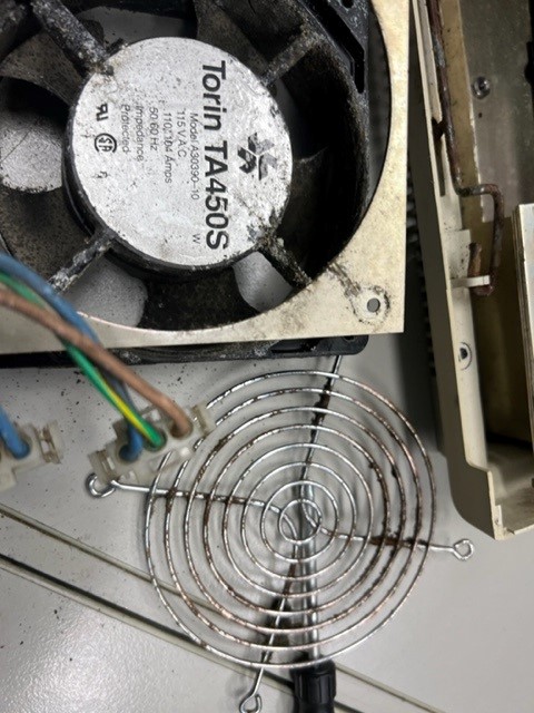
some success
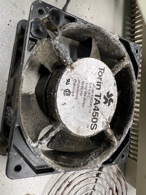
Fan is back in and tried to power on. Nothing…
You need to remember to plug the fan back in and then power on or nothing happens
Ok so we have power on the base unit.
I plugged a keyboard in now and can hear something happening but nothing shows on the screen but when i press keys on the keyboard i can hear a slight click noise.
Back to basics
check the video connections on the cable are right
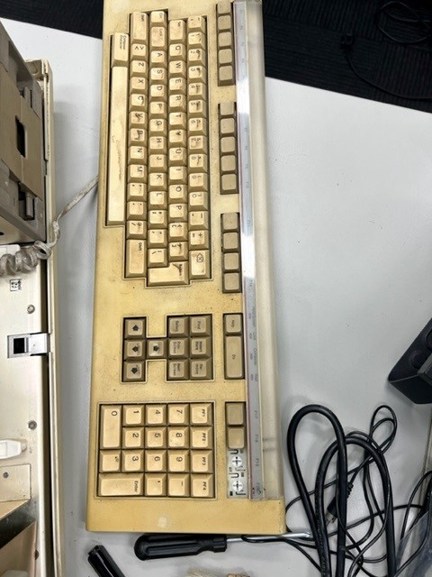
check it is the right keyboard
3 clean the floppy drives and then try a floppy disc to boot
This machine is doing my head in
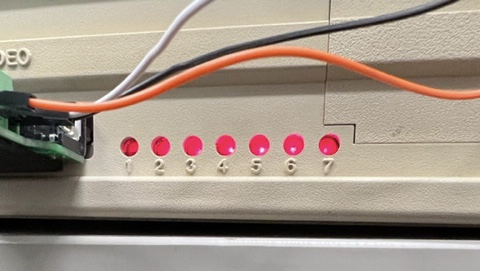
At the back there are seven led diagnostic
It shows what the error is and how to resolve
Currently ALL seven are lit, grrrrrrrrrr
This is going to a pain
Time to pull it all apart
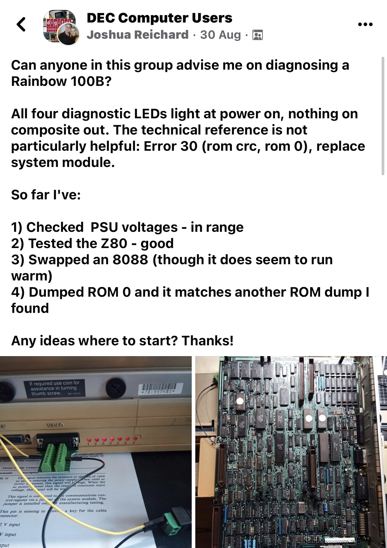
Thank you! I would appreciate following your progress and I will share mine as well. My next step is to probe the DRAM chips and possibly replace them with socketed 6416 chips. My hunch is bad memory is preventing the ROMs from loading to execute initial code. Best wishes!