Well, of course the good fortune couldn’t last.
Started installing the IC’s as per the construction guide, and pretty soon hit a snag.
The clock circuitry wasn’t provising the all of the right clock signals. Some were present, but not all. Basically the TPAL wasn’t putting out what was in the guide. The guide however was made before the 15 Mhz upgrade was available, so I thought maybe the new TPAL didn’t put out all the same clock signals and pressed on.
I got to installing the MC68000, and the tests just didn’t work. There’s a set of 4 switches that set the test/run mode. In one of the settings, it’s supposed to flash the diagnostics LED (LED1) and the relay for the casette control is supposed to click.
I proceeded walking through (but not following) the instructions anyway, looking to see what was coming up, thinking it might reveal what the problem was.
First thing I noticed was that they wanted you to put on some of the jumpers and I realised that a bunch of the tests would fail cos the jumpers change the operation. I had stupidly left all the jumpers still on the board, even though I documented their positions previously. I removed all the jumpers on the board, and this restored the clock signals on the TPAL, or so I thought.
The diagnostics still failed. Once again, I proceeded walking through the guide and only right near the end did I spot my error. As I was walking through, I’d take the chips I’d removed and were supposed to put on the board aside. I got near the end and had a 74F74 instead of a 74LS74. I thought that was odd and reviewed all the 74F74’s that should be installed on the board.
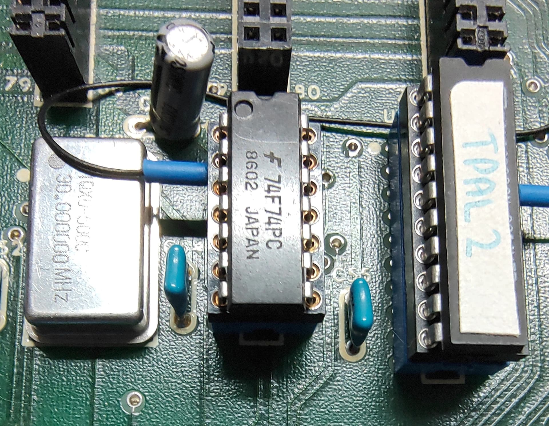
Turns out the very first chip I put in the board, instead of being a 74F74, I inserted a 74LS74. This is hooked to the 30 Mhz oscillator that all the clock signals are derived from. It was just not quite fast enough to deal with the 30 Mhz clock signal, so none of the tests worked.
Pic of the offending chip, between the 30 Mhz oscillator and the TPAL:
Thinking this was the end of it, I proceeded onward, getting eventually to the video test.
I can see “something” occasionally, but it’s just not syncing. At this point, I suspect maybe the GBSControl simply wasn’t finding video mode I wanted properly (basically EGA), so I decided to download the latest version of the code and update my GBSControl.
Still the same thing. I suspect that it’s just not seeing the signal properly. I tried another monitor as well, but still no luck. From what I see from the monitor output, it just won’t do 15.7kHz @ 50 Hz,m and the GBSControl isn’t doubling that to 31.4 Khz.
While looking over the board a second time, I noticed that a a lead on a small 56pf capacitor was broken. I also noticed the one next to it was broken as well.
Pic of broken caps:

Pic of caps replaced:

This however didn’t change anything with the machine working.
At this point I’m a bit stuck. It’s like things are running but the video is just not being decoded properly by the GBS Control. I don’t really have any other option (working) in the way of a screen at the moment. I have an IBM 5151 screen, but at the moment it’s in need of installation of some replacement caps (which I have), and a few parts of the case need a bit of work with some araldyte. That said, the machine it’s off (an IBM5160) still needs a lot of work so I could test the monitor. Also means if if something there doesn’t work, I won’t necessarily know what is at fault.
Also not 100% sure that the Applix1616 will drive the screen at the right sync rates. It supports mono, but nothing specific mentioned.
I’ll need to have a think about this. I might remove most of the chips and go at a much slower pace through the testing/build document again, especially now I’ve resolved the clock issues.
Will also reach out to some local (Canberra) people and see what options I have to borrow a suitable known working monitor.