Didn’t quite get as much done as I wanted, but thought I’d post an update.
Pulled all the IC’s out of their sockets. Fortunately everything is socketed. Then I filled in the vias and blank pads. Lots and lots of vias. About 2 hrs all up (with regular breaks). Having thin solder (0.35mm) really helps in just adding the right amount to each via/hole.
The 0.35mm solder is my go-to for fiddly jobs, tho I have 0.56mm and 0.8mm on hand for those bigger joins.
Board with vias filled but before cleaning:
Some of the original joints don’t have enough solder, particularly on ICs. It seems to be a common problem spread across the board - Many are good, some are not quite so good. While these are probably electrically sound, I’ll touch them up after cleaning the board.
Closer pic of some of the sub-par solder joints, plus you can see all the excess flux:

After cleaning the PCB, everything looks MUCH better (used Servisol Electronic Circuit Board Cleaner - NA-1008). There’s still some residue on the board, but I’ll wash the board with isopropyl once I’ve touched up all those sub-par joints. Note that I only cleaned the solder side, as the component side was already fairly clean.
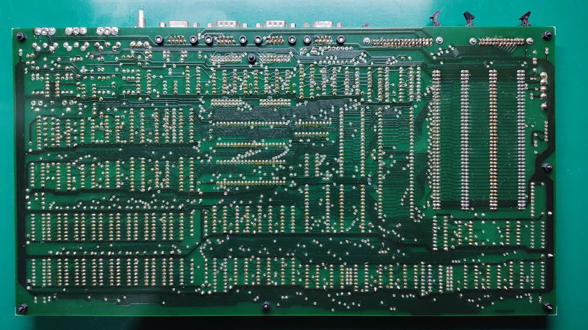
Board after cleaning with Servisol:

Soldering bodge wires to the machine sockets was… somewhat challenging. Having multiple pairs of fine tweezers with different shaped tips/bends helps immensely. I bought extra sockets of each type just in case I made a mistake along the way, though in the end I didn’t need them. Used a different colour for each bodge wire, which helped immensely to ensure that I got all the wires connected to their correct places. To aid in the mechanical stability of the wires where they come off the sockets, I’ve been using a small amount of insulation off some larger wire over where the bodge wires get soldered to the pin of the machine socket. A tiny bit of superglue holds the insulation to the body of the socket, keeping it nice and stable. I didn’t have any heatshrink small enough for the job, something I’ll have to rectify for future restoration work like this.
Soldered 74LS08/TPAL/R6545 socket harness:

To 100% ensure that the shortened ends of the machine sockets don’t touch the normal IC sockets underneath, I used small pieces of a PVC based high temp tape that I’ve had about for a while, to act as a physical barrier. I was going to use Kapton, but I couldn’t find my small roll of it, only the large (200mm wide) one, which would have been even more annoying to deal with. The PVC tape is rated to about 200°C, which given that the joints underneath the sockets shouldn’t need to be soldered again, should be more than ample to the job.
R6545 socket with tape over pin 21:

And here’s the board pretty much ready for all the chips to go back in. I laid down the extra resistor that goes between the 74LS32 and a track that eventually goes to the RAM, and joined that with a small piece of bodge wire. I also opted to solder the 2 remaining wires from the 74LS08 directly to the vias as before. I considered putting DuPont header pins into those vias and then trying to crimp a matching female header on the wires, but I suspected that trying to get the 30AWG bodge wire crimped successfully into the female header would be troublesome. I have the right tool, but the pins are really only suited for 24-28 AWG wire, so this would just be a bit too thin. Fortunately, as everything else is now all sockets, I could redo this later down the track with slightly thicker wire and replace that whole harness (especially as I have more sockets).
Board with all the machined sockets installed, but without the ICs installed:

I tested continuity on all the bodge wires, as well as between adjacent pins and between the sockets and the blocked pins underneath. Everything passed 100%, matching what the 15 Mhz upgrade guide says needs to be done (found thanks to ChickenMan and the Microbee Technology Forum).
Things to do next:
- Start testing chips on the memory expansion and disk controller boards, plus detail what cleaning/remediation is required for those.
– I should be able to do some of this in between the various other bits below as I have time/need a break. - Put motherboard back into the case.
- Review the motherboard settings.
– Specifically check the memory settings. When the memory expansion board is installed, the on-board memory is actually shifted upwards in the memory map. As I intend to power on the machine initially without the memory expansion, it would be good to get this right. - Power on test without chips installed.
- Follow test guide (loosely), installing certain chips and doing tests to see if everything is behaving.
- Full power on of just the motherboard with monitor (using a GBSControl to take the EGA output to VGA).