Thanks for reminding me to register epooch!
So, made some more progress.
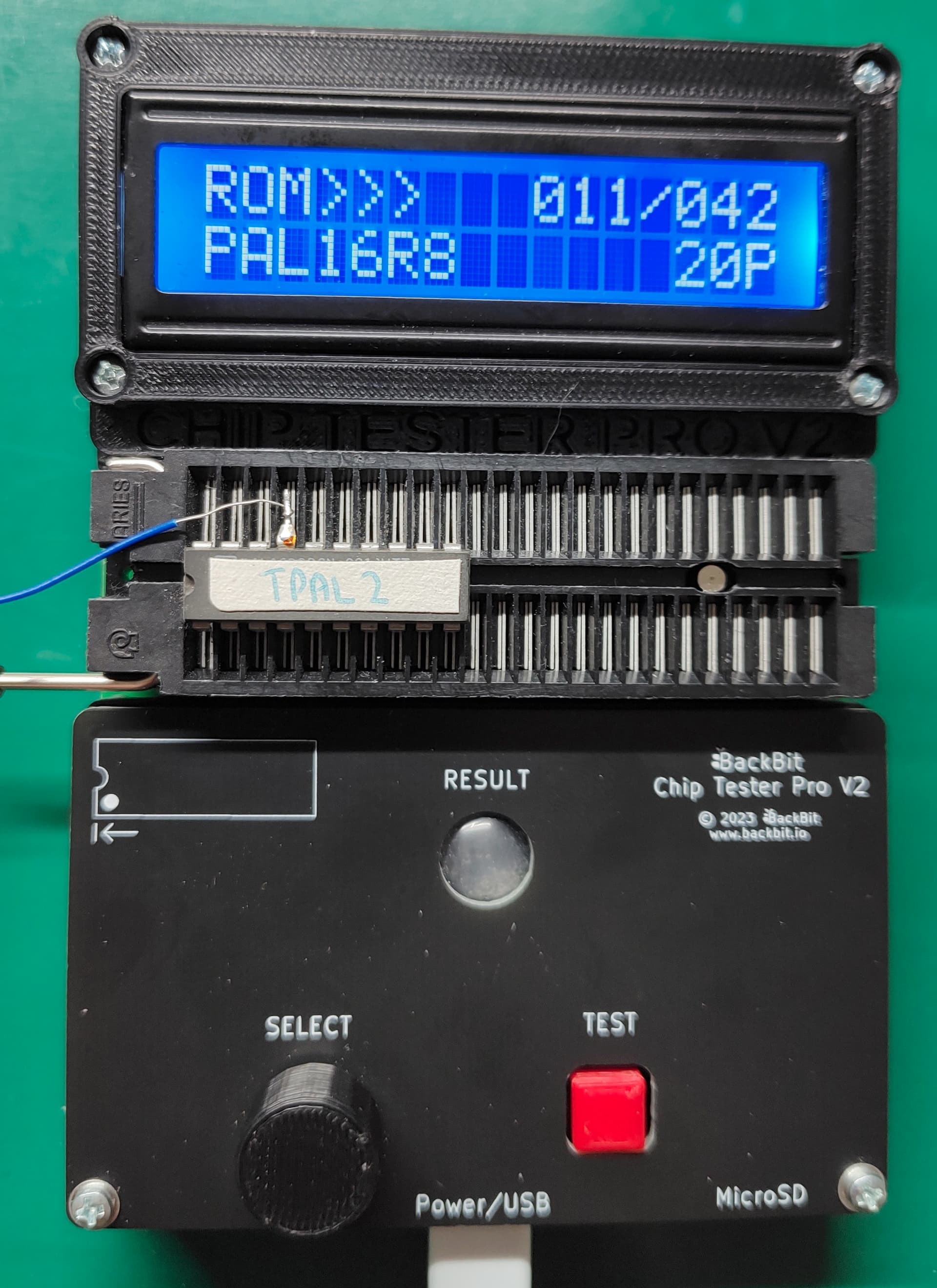
Ripped TPAL (PAL1) and VPAL (PAL2). The TPAL is V2 (timing, related to the 15 Mhz mod), while the VPAL is V5.
Didn’t want to bend the pin on the TPAL yet, so used a bodge wire to connect the upturned pin to the Chip Tester for ripping:
Tested Ram & LM319. All passed!
Cleaned the top and bottom of the case. Also replaced standoff screws with nylon ones and added in 2 extra nylon standoffs that were the same height around slot area to support the motherboard when cards are installed/removed.
- One of the nylon standoffs does not screw through the board, but sits between Slot 3 and the MC68000. It’s the one in the middle, just to the right of the rear card slots. There was already a hole in the case, but it doesn’t line up with a matching hole in the board, so using a nylon standoff provides support without causing an issue by shorting something out.
- Plan to use the replaced screws elsewhere, since a number of screws were missing. None of the holes are plated or grounded, and the nylon screws avoid marring the case or the motherboard surface.
The nylon hardware is black, while the original metal hardware ones are nickel coloured:

Populated the 2 remaining expansion slot connectors. The 80 pin header connector was no longer available, so had to use 2x 40 pin headers instead. To get them to fit, needed to sand down one end (used 600 grit sandpaper). Also decided to touch up all the existing slot connections while I was at it, since some didn’t seem to have enough solder on them.
Top tip: Sand down the flat end of the connector! Usually one end has an injection moulding mark (where the sprue is). You do not want to sand that end down as it’s not as flat, plus in some cases it’s usually marginally thicker. All of that makes it hard to remove the right amount of plastic from the ends while keeping it square to the rest of the connector.
Pic of sprue end of connector:

Part way thru soldering the connectors:

Added screws/nuts to connectors on the back to avoid bending, as they are on the edge of the board:
- Joystick/Serial/Video connectors. Metal hex screw on top with plastic nut underneath. M3 hardware.
- Centronics/User IO port connectors. Metal hex screws with on bottom (with washer), with metal nut on top. M2 hardware (M2.5 would have been better).
Touched up the solder joints for all the edge connectors. While doing the cassette/speaker/keyboard DIN connectors and the power connector, spent the time to make them actually line up a bit, as they were all pointing slightly different directions previously, or not at right angles to the board.
Added more solder to the joints for the reset switch pins, as the switch would move up and down if you touched it. Also bent over the pins over the edge of the board to give it some mechanical rigidity. Usually a design would have these go through solder holes to provide a physical connection to avoid movement.
Half way through bending the pins on the switch. Left pin is standard, right pin has been bent, plus you can see the one of the nylon nuts on the bottom of the board for the Joystick connector:

Cleaned up the solder on the 74 series chips that had legs bent for bodge wires, using the 74 series chips as the guinea pigs for this process. Leaving the solder on the pin would make bending them back harder, plus may not allow the chip to sit properly in the new machined sockets. Once I bent down the pins, I put them through the ChipTester Pro. One worked (1 pin re-bent), the other failed (3 pins bent). A bit of cleaning and some testing however revealed that the issue was the old flux (rosin) and the new flux (no clean rosin) together formed a conductive layer! Once cleaned, the failed chip was working again. This means I’m definitely going to need to clean all the flux residue off the board before I attempt power-up.
Solder cleaned up prior to bending the pins back. Make sure to clean solder off both sides, and also any flux:

I’ll probably break out my solder sucker (an electric pump one) and use this to clean the solder off all the bent pins, rather than using solder wick. Fortunately there’s only 2 more chips (MC68000 and R6545), and each of these only has one pin bent. Will replace both the 74 series chips with new, just to avoid any potential issues.
I also tested the power supply and so far it’s working fine, putting out the right voltage on each pin. When you turn it on and turn it off, it emits a tiny low volume high pitched squeal (>16 Khz - I might be in my 50’s but I can still hear that high) for less than half a second. This is from the high frequency switch-mode supply startup/shutdown, so I’m not TOO concerned at this point, but I’ll probably do some more testing, just in case.
I’ve also prepared all the machined sockets to implement the bodge wires. After trimming the pins, I filed them slightly to avoid any possible connection to the socket underneath.
Machined sockets for the R6545 and the MC68000 prepared:

Top of board. Looking much better:

Bottom of board. Looks better but will definitely need to clean off that flux residue:

Things to do next:
- Solder up all the vias and unpopulated solder holes.
- Redo a bunch of solder joints on the bottom of the board.
– Lots of joints here that don’t have enough solder on them. Definitely not the greatest solder job. - Clean all the flux residue from the bottom of the board.
– This is why I’m going to fill in all the vias and solder holes, as otherwise cleaning the bottom will just spread all the flux residue onto the top of the board. - Clean and re-bend pins on R6545, MC68000 and TPAL.
- Implement bodge wires on the machined connectors.
- Start testing chips on the memory expansion and disk controller boards, plus detail what cleaning/remediation is required.