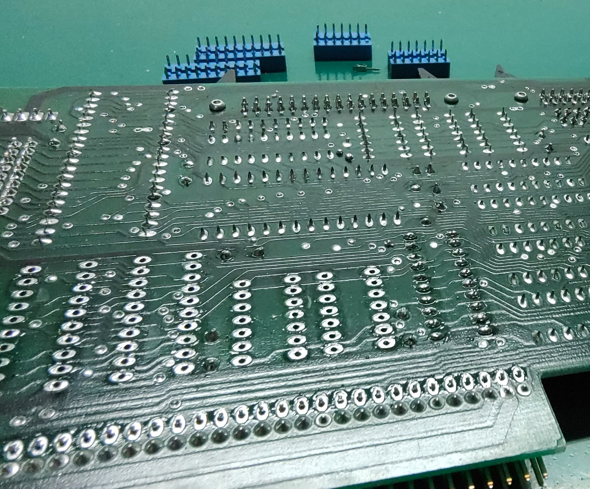
Touching up the soldering on the Disk Controller has evolved into using my vacuum desoldering station to remove a lot of probably bad solder from the board. ![]()
When I tried touching up the soldering around the sockets, there were a lot of joints that just didn’t want to take solder well. I switched to doing all the passives (caps/resistors/headers) and apart from the big 80 pin header on the board edge, most of these went fine and didn’t require any extra work.
My guess is that the person who assembled this board ran out of solder during the assembly (possibly while doing the 80 pin expansion connector) and switched to a different roll, which was contaminated in some way. As a result, I’m removing most of the solder, particularly from the sockets, using my desoldering station and will reapply new solder. Note that I’m just aiming to remove the existing solder. I’m not deliberately trying to remove any sockets from the board, so I don’t need to make sure I’ve removed all the solder from a joint. Just enough to allow me to make a new good clean solder joint. That said, a lot of them are coming off (and a socket pin fell out of one of them), so I may just replace many of the sockets with new ones, since I have some on hand. The blue sockets look nice on the board, but I’d much rather have working sockets.
Part way through some desoldering:
Some desoldering station tips:
- Hold the PCB at right angles to the table, rather than leaving it flat on the table.
– This way, you’re not fighting gravity to pull the solder out of the joint/board. You’re just pulling the solder out of the joint/board. - Put the nozzle over the joint, wait for it to melt, pull the trigger. Once you’ve sucked away the solder, pull the desoldering gun away from the board before releasing the trigger. I usually release the trigger about 1/3 to 1/2 second after removing the gun from the board.
– This allows the nozzle and barrel of the desoldering gun to clear properly, since it should no longer be blocked by the board/component/joint, allowing more pressure to pull any remaining solder in the gun through the barrel. It also helps avoid the back half of the gun barrel (which is colder) clogging with solder, which is a right pain to clean out.
Over 100 joints worth of solder out of my desoldering station (after cleaning):

Just a note on my desoldering station:
I’m using a Yihua 948-I desoldering station, but I’ve modified it slightly. The pump motor in these gets run through a somewhat odd driver circuit that limits the max voltage to about 10.5V. As a result, the suction isn’t very great, which is a well known problem with these units. The actual pump motor is normally rated at 12V, and can be run up to about 14V without it causing too much of an issue (listed as 9-14V).
There’s no feedback circuitry on the motor (eg: stall detection), so I’ve made up a small board that is mostly just an opto-coupler and a MOSFET, so that I can use the existing motor output to drive the motor from an external supply connected to a barrel jack on the back of the unit. Running it at 12V provides a fair bit more suction than the default, and if I wanted I could make the voltage slightly higher (eg: 14V). I did look to see if I could power it without an external supply, but the built in transformer simply can’t supply the power, even if you use a voltage boost circuit.
I only made 5 of these boards (JLCPCB for the PCBs and used components I had on hand), and I’ve given 2 away already. There’s not much to it (opto-coupler, diode, 3 resistors, MOSFET and a bunch of connectors). There seems to be a bit of interest, so I might spin up a V2 with more commonly available components and put it up somewhere.
Inside of the Yihua 948-I with the first version of the little driver board installed to the left of the pump motor:

During breaks in desoldering, I’m reviewing the circuit diagrams (as limited as they are) for the motherboard, disk controller and memory/SCSI expansion, so I have a better idea how things sit together and what sort of basic tests I can perform on boards before I even get to powering the disk/memory boards up. During one of these reviews, I noticed that the DE9 serial connectors on the back of the Applix motherboard and on the Disk Controller are NOT the standard wiring for DE9 serial!
Applix DE9 serial connector wiring:
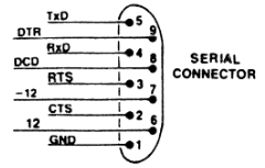
Of the various types of null modem cables I have (I have lots), one would have shorted +12V to -12V, while another would have shorted +12V to Ground, and a third would have shorted -12V to Ground. None of these outcomes would be useful at all!
So what I’m most likely going to do is:
- Cap off these connectors (with some plastic covers that screw over the socket) so nothing can be inserted in them without deliberately removing the cover.
- Make some cable harnesses that connect the 2x9 way headers (SJ*-0) to correctly wired serial connectors, which I’ll then mount on the back panel.
This will mean some of the plate covers I laser cut will not actually be needed, but that’s not a huge problem to have. That said, I might be able to repurpose them as part of the cover to block the existing ports, at least until I sort out something more long-term like a 3D printed cover or removing the on-board serial sockets altogether.
On the monitor front, I hopefully should have an RGB CRT monitor in my hands either late this week or early next week. I’ve still got the RGB2HDMI on the way, but it’s coming from the US and UPS has still not picked it up from the supplier.
As for other peripherals, the Applix1616 uses an XT keyboard. It won’t work with an AT one, unless it has a switch to support XT. I have 2 possible keyboards I can try.
The first I one have is a genuine XT keyboard (the Model F off my IBM 5160). The case is cracked in 2 places (right front corner and the bar between the F10 and Alt keys) and I don’t know for sure if it is electrically sound. So that’s the next thing I’ll be tackling, which apart from repairing the case and confirming the insides are OK, will involve giving the keyboard power and using a cheap logic analyser to see if it generates the right clock/data signals when keys are pressed.
IBM Model F keyboard with cracked case:

The second keyboard is a switchable XT/AT keyboard. When I tried this with the Applix originally, it didn’t seem to work, so I am going to perform the same test on it as well. Hopefully one of these keyboards will work, else I’ll have to see what else I can find.
For reference on the differences between XT and AT keyboards: DOS Days - XT and AT Keyboards